Simon Tilts Assembly Guide
 QCPete
 Introduction
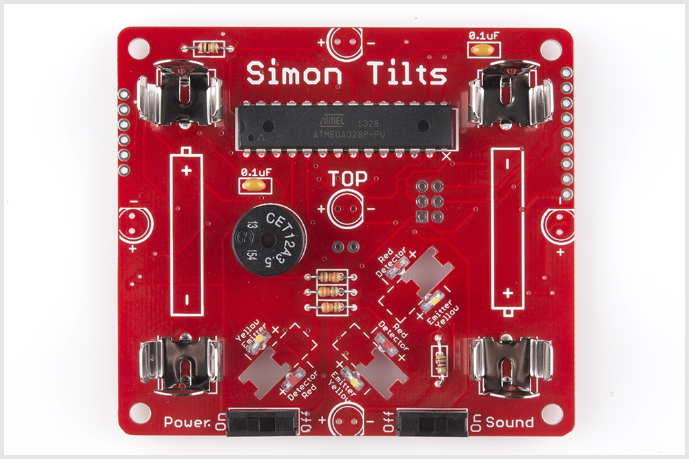
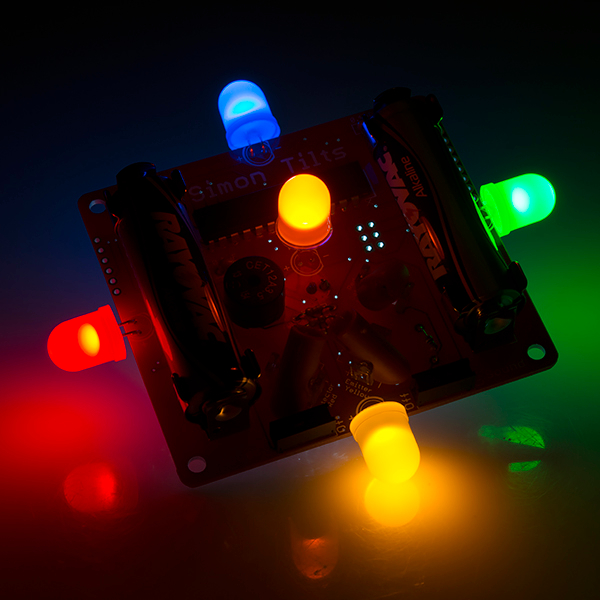
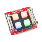
Simon Tilts is a memory game very similar to Simon Says, but instead of pressing buttons, the player is challenged to rotate the device in a specific pattern. It comes as a PTH soldering kit, and it's up to you to solder it all together! You can buy the complete kit at SparkFun!
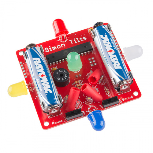
If you're new to soldering, the Simon Tilts PTH Kit is a great place to start. This assembly guide will take you through each component in the kit and show you how to solder it into place.
Suggested Reading
If you'd like more general knowledge about PTH soldering, then we suggest checking out these following other tutorials:
- How to Solder - Through-hole Soldering
- Decoding Resistor Markings
- Diode and LED Polarity
- Electronics Assembly - Washing
- Video - SparkFun Infrared Sensor Overview
Necessary tools and supplies
Suggested additional tools and supplies
- Safety Glasses
- Flux Pen
- Solder Wick
- Scrubbing brush (an old toothbrush works fine)
- Deionized water for cleaning (or you can get away with tap water)
Quickstart - Your First Component
Locate the 10KΩ Resistor. It has a specific pattern of stripes on it: BROWN, BLACK, ORANGE, GOLD.
It looks like this:
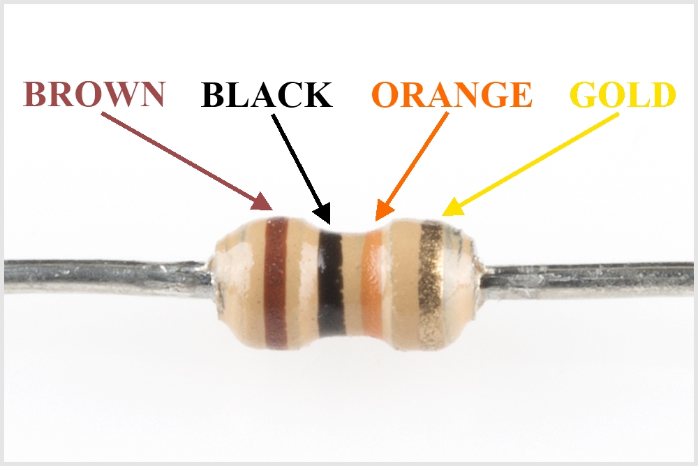
Note, the patten can be in the opposite order; this is still the correct resistor.
To further understand resistor markings, please check out the following tutorial: Decoding Resistor Markings
Bend the legs downward.

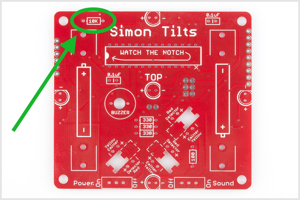
Locate the 10KΩ Resistor position on the board.
Insert the resistor into the PCB. Note, this component is not polarized and so it does not matter which leg goes into each hole. Some components on this kit are polarized, and we will take extra care when we get to them to ensure they are plugged in properly. To learn more about what it means to be polarized, please check out this tutorial: Polarity
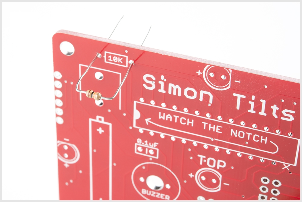
Push the resistor in so it is nearly flush with the board.
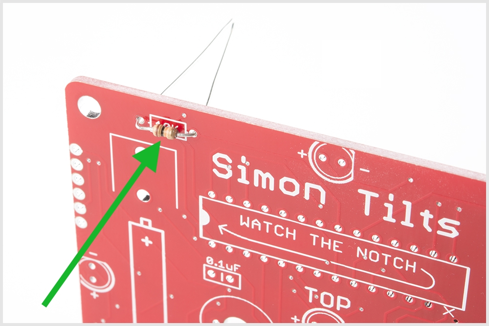
Slightly bend the legs outward to hold it in place.

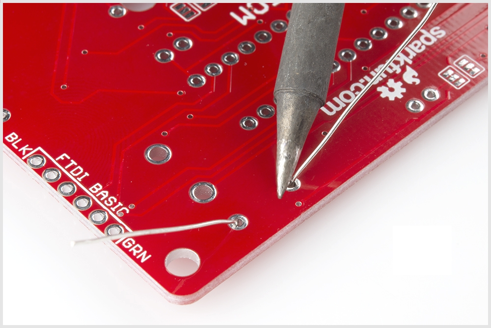
Flip the board over. Hold the soldering iron's "Sweet Spot" so it touches both the leg and the metal ring. Hold for 2 seconds.
Feed solder into the joint.
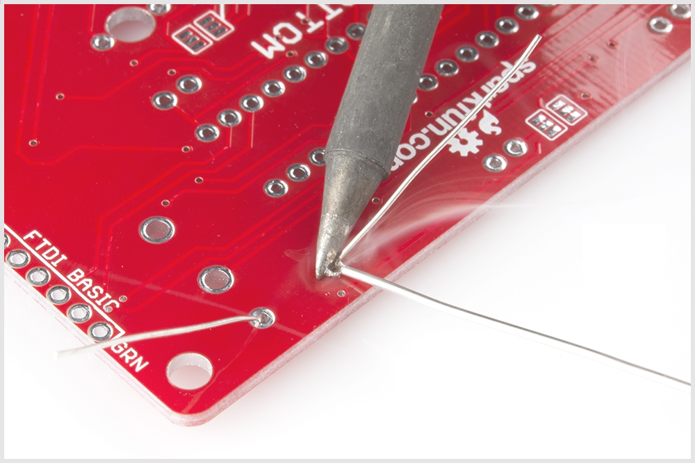
First, pull away the solder.
Second, pull away the iron.
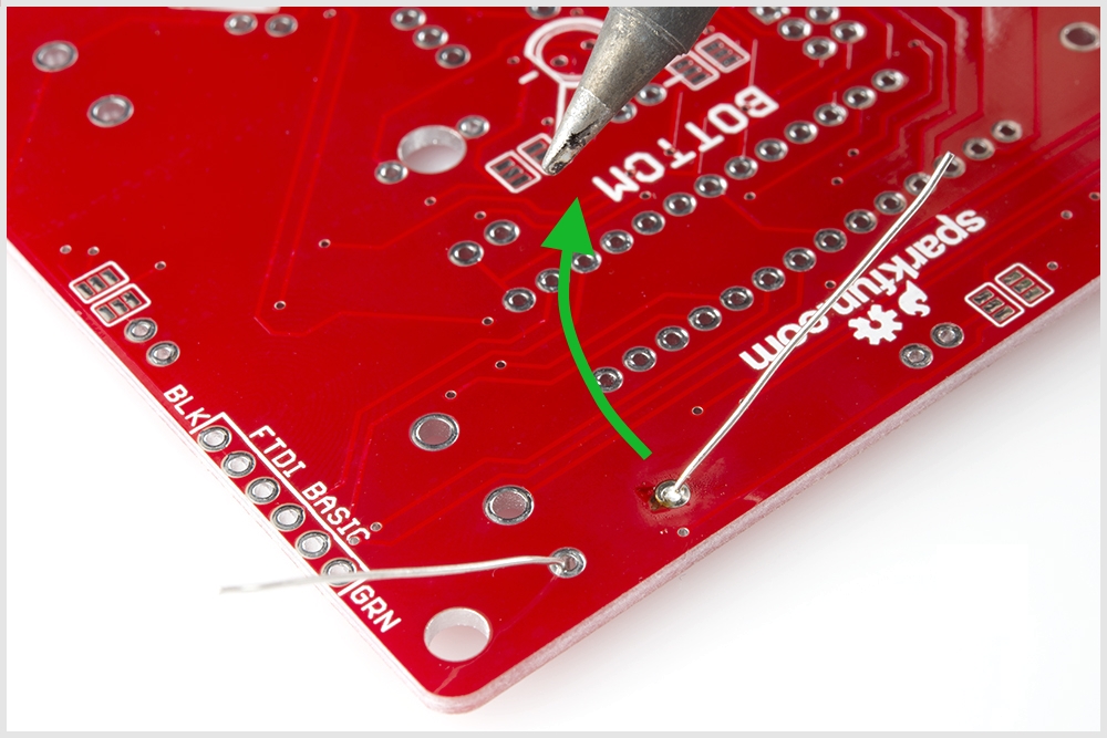
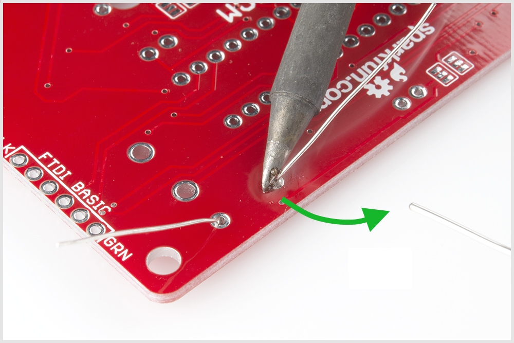
Your solder joints should look like this - a tiny volcano.

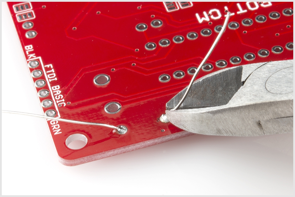
Clip off any excess legs.
The Other Resistors
Now that you've successfully soldered in the 10K resistor, you're ready to begin soldering in in the remaining resistors.
Note, before soldering in each resistor, double check you have the correct value by ensuring that the color markings are correct.
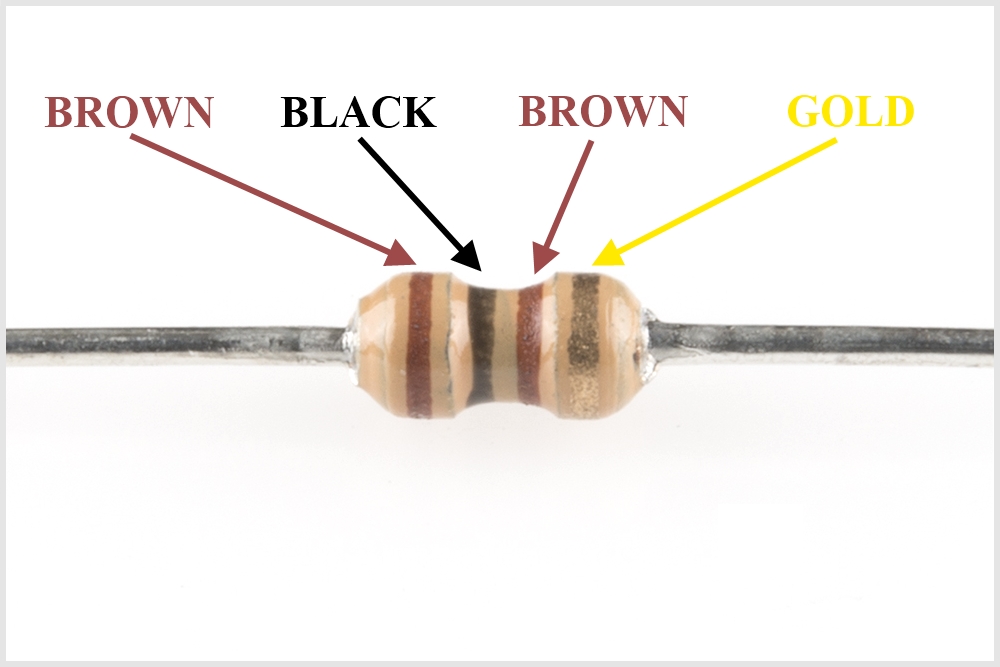
Locate the 100Ω Resistor. It has this pattern of strips on it: BROWN, BLACK, BROWN, GOLD.
A 100Ω resistor looks like this:
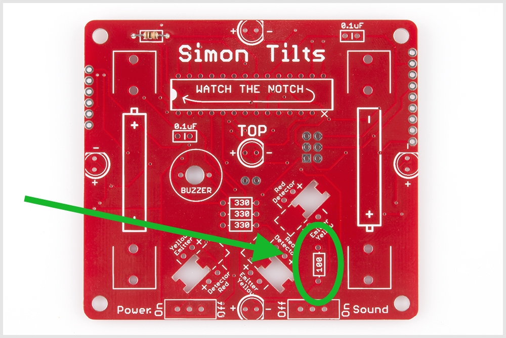
Locate the position on the PCB:
Using the same methods you learned with your first component (the 10KΩ resistor), solder into place, and trim the extra lead length.
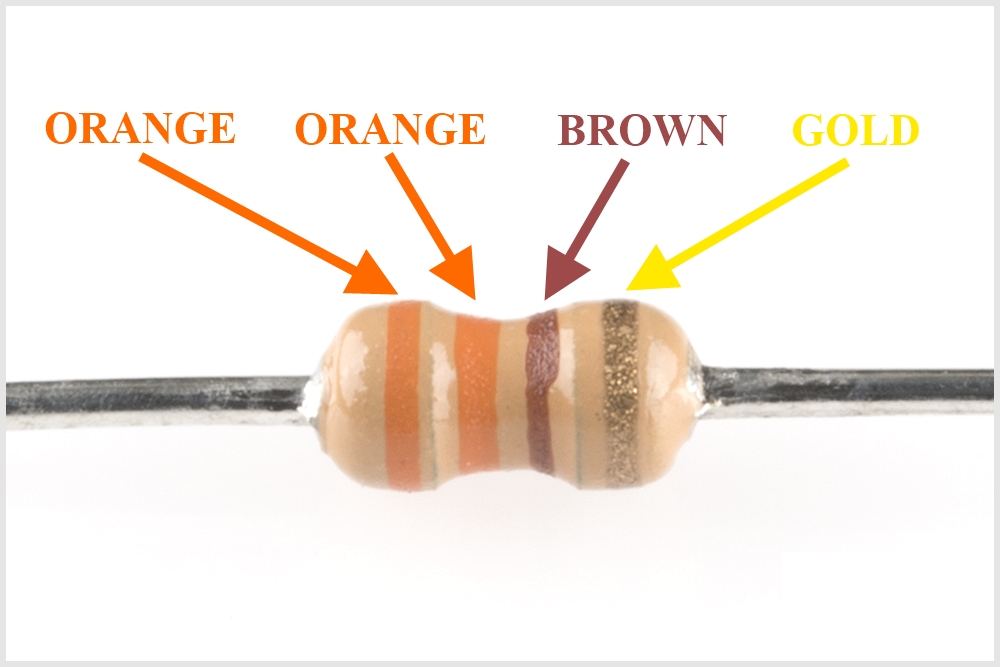
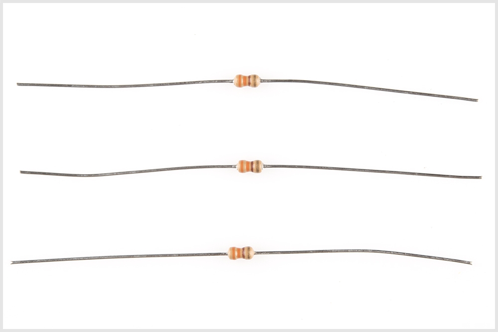
Next, locate the 330Ω Resistors (x3). They each have this pattern of strips on them: ORANGE, ORANGE, BROWN, GOLD.
A 330Ω resistor looks like this:
There should be three of them:
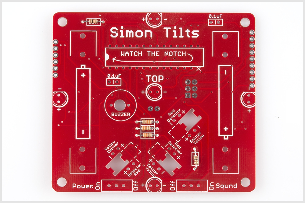
Locate the position on the PCB:

Using the same methods as before, solder into place and trim the extra lead length.
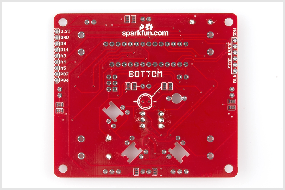
When you're done soldering these remaining resistors, your board should look like this:
TOP:
BOTTOM:
Capacitors
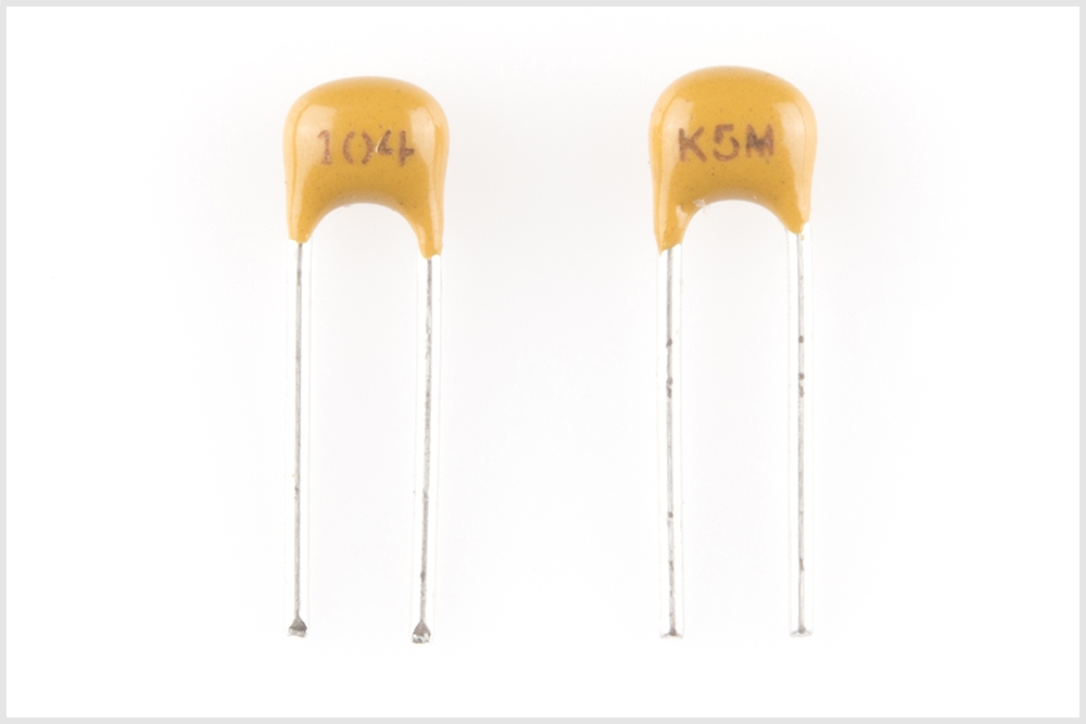
Locate the two 0.1uF capacitors. These look a little different than resistors. They have two leads than come down off the bottom of the component, and they have the markings "104" on them. (also note, the bottom side may have some other letters, like "K5M")
They look like this:
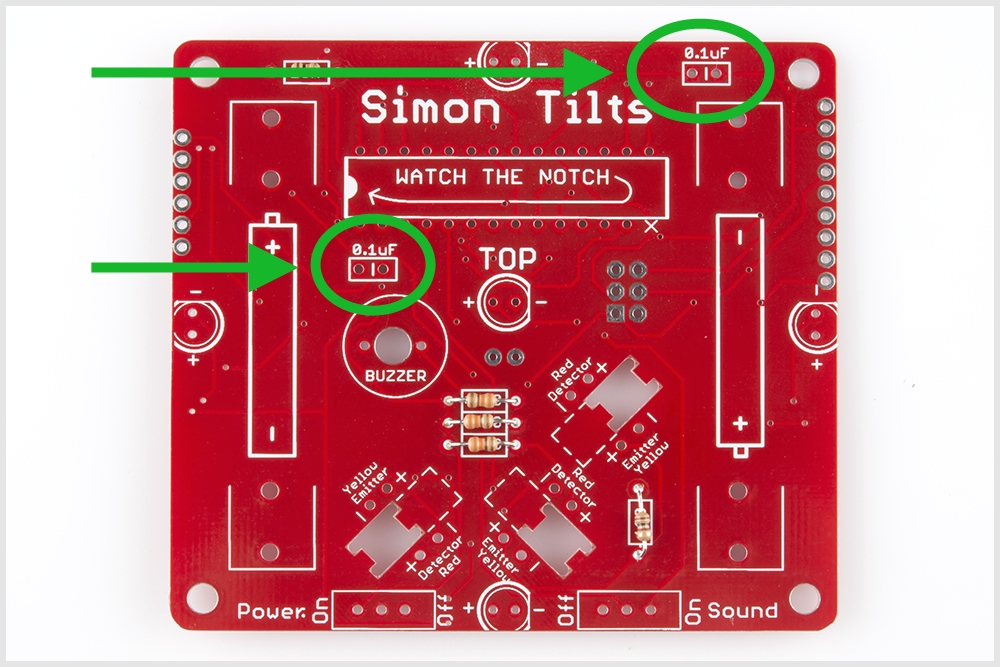
Locate their positions on the PCB:
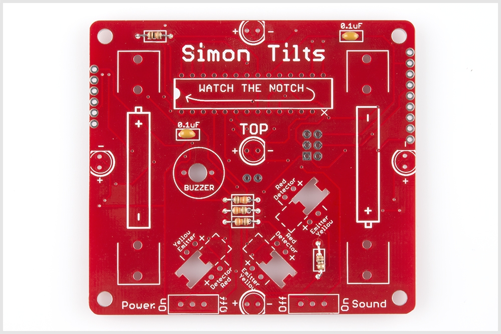
Ensure that they are flush with the surface of the PCB and standing upright. Solder them into place and clip access lead length. When you're done soldering these into place, your board should look like this:
The Microcontroller
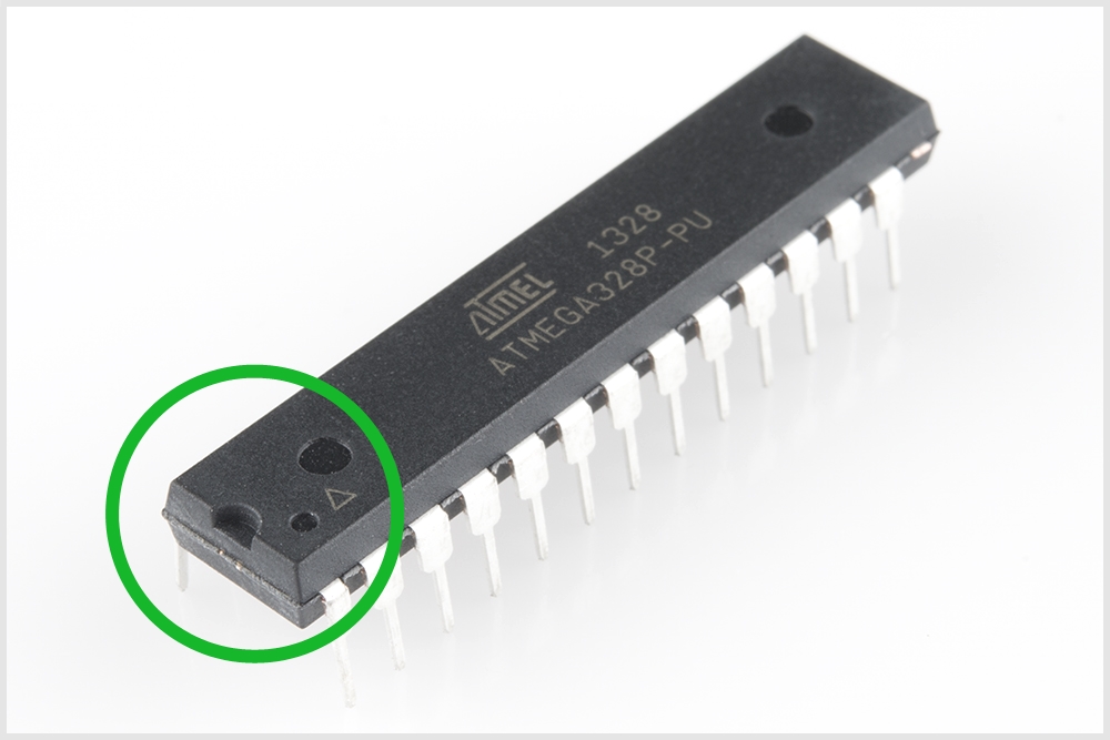
Locate the Microcontroller. This component is polarized, which means we need to take extra care to place it in the board properly. Notice the notch:
Now locate the position on the PCB. Again, notice a similar notch symbol in the PCB white ink:
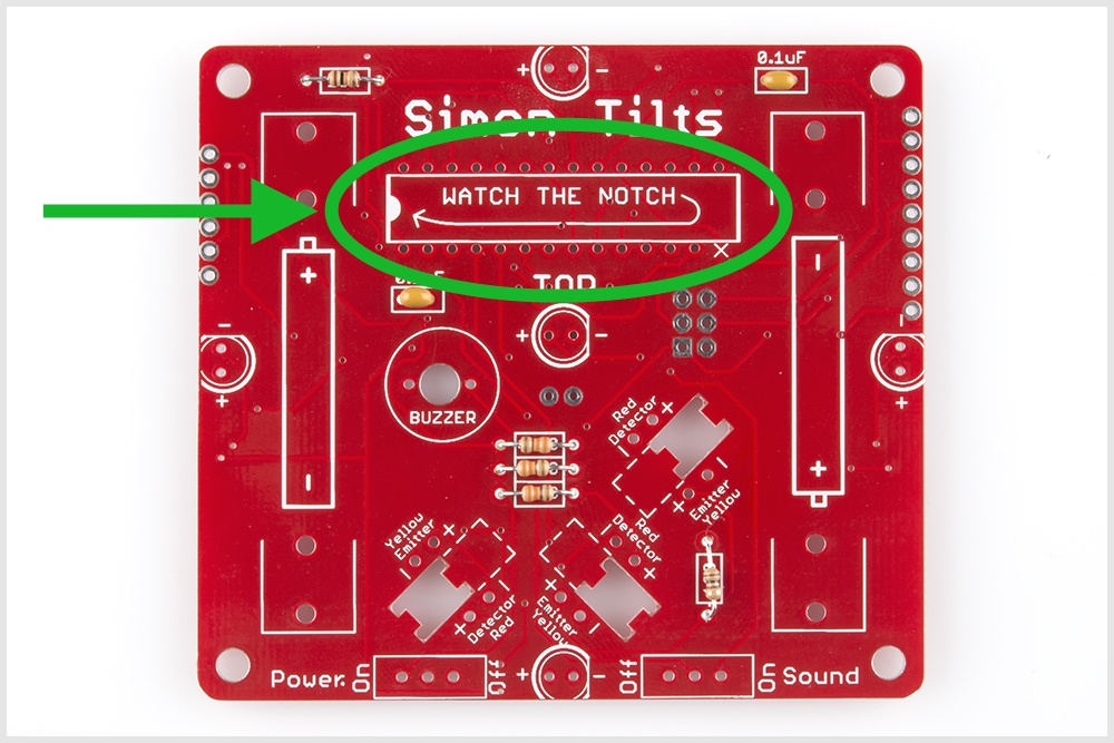
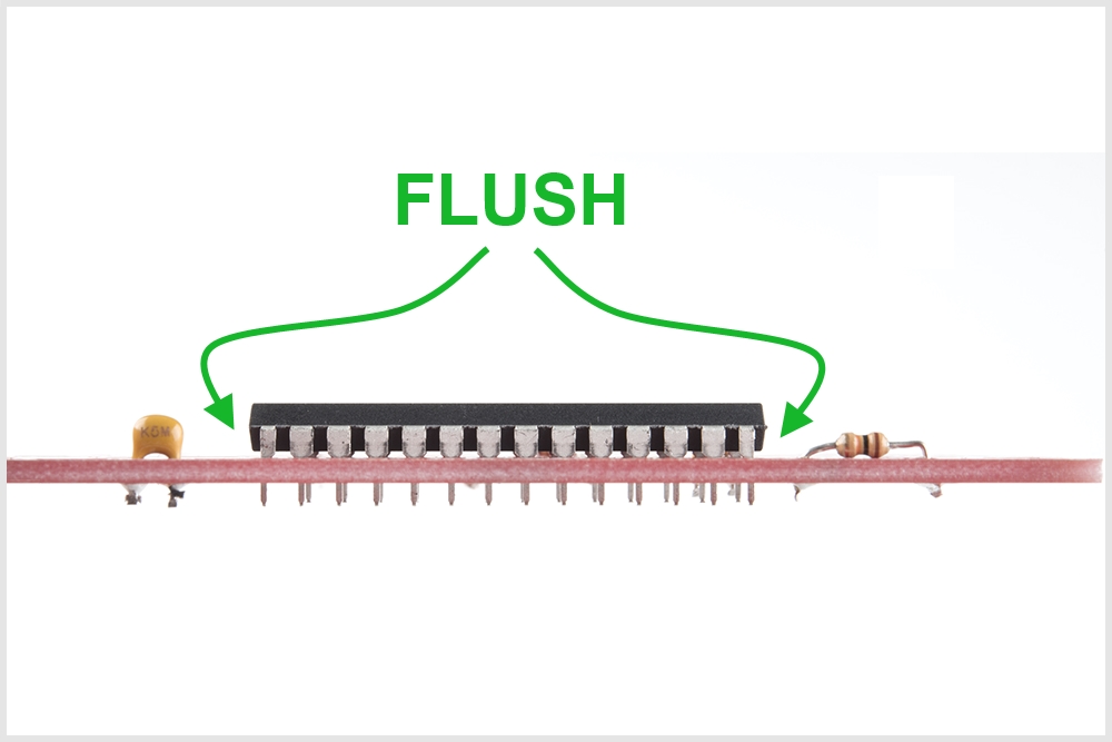
Taking care to align the notch properly, place the ATmega328 into the PCB. While soldering the first leg (it can be any leg you choose), make sure to keep the component flush with the PCB.
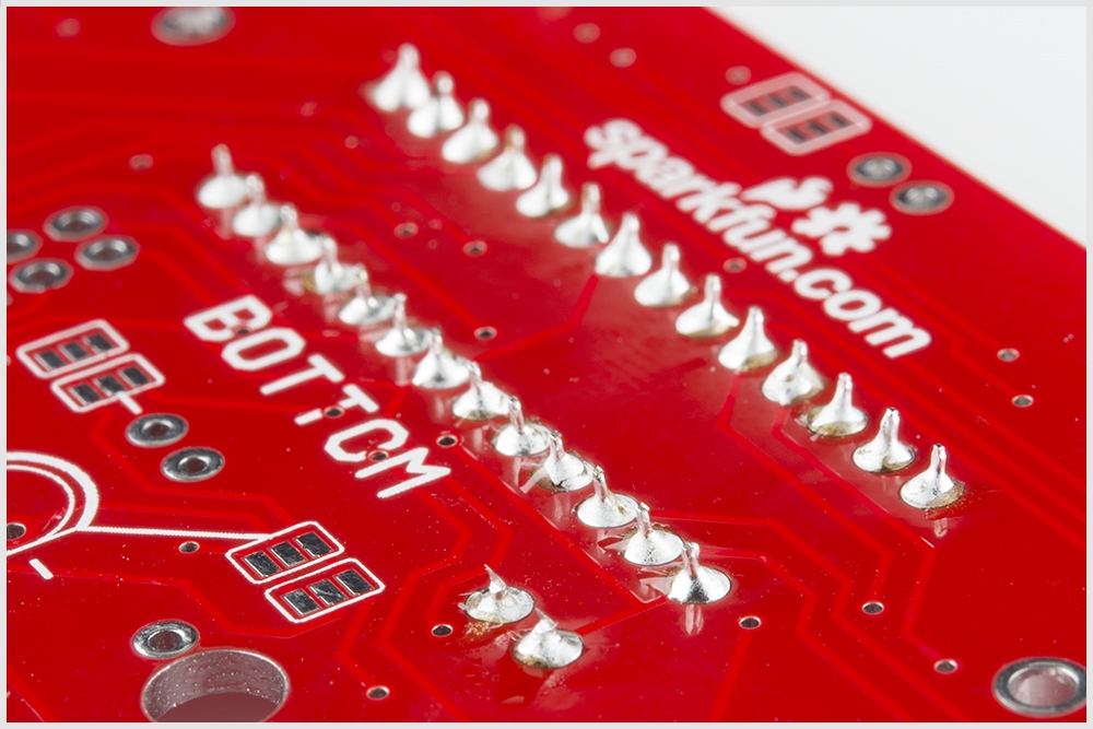
When you're done soldering this component, the bottom of your board should look like this - a nice row of even volcanos:
IR Emitters and Detectors
Careful, these next 6 parts are polarized and need to be placed into the PCB properly. To learn more about polarization, please check out this other tutorial: Diode and LED Polarity
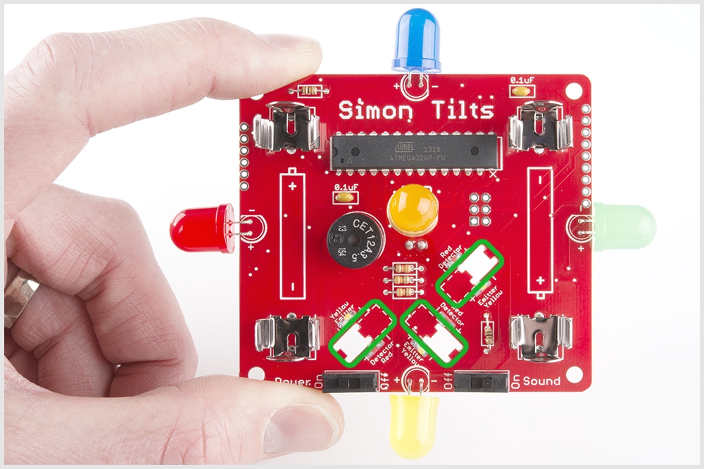
Locate the IR emitter and detector pairs:

There should be 6 total pieces. Three with red dots, and three with yellow dots:
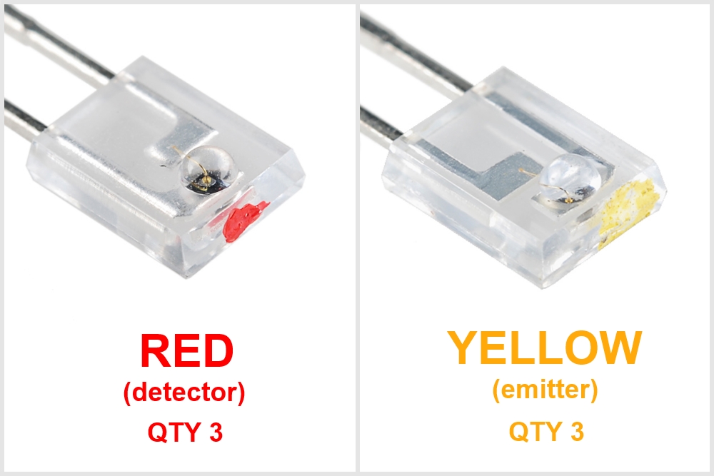
These are polarized parts, so this means they have a "-" and a "+" leg.
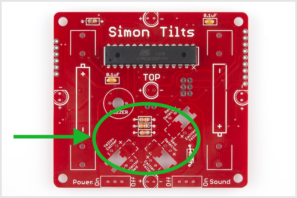
Locate the positions on the board. Notice that there are "Yellow Emittor" and "Red Detector" labels printed on the PCB. Also note that there are "-" and "+" marks for each leg. Be careful here to ensure correct placement and polarity.
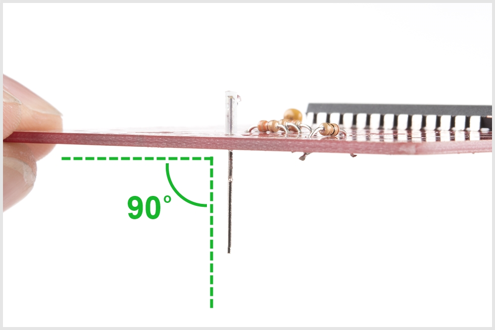
When soldering these into place, make sure they are positioned straight up (vertically). Check that your legs are forming a 90 degree angle with the PCB like so:
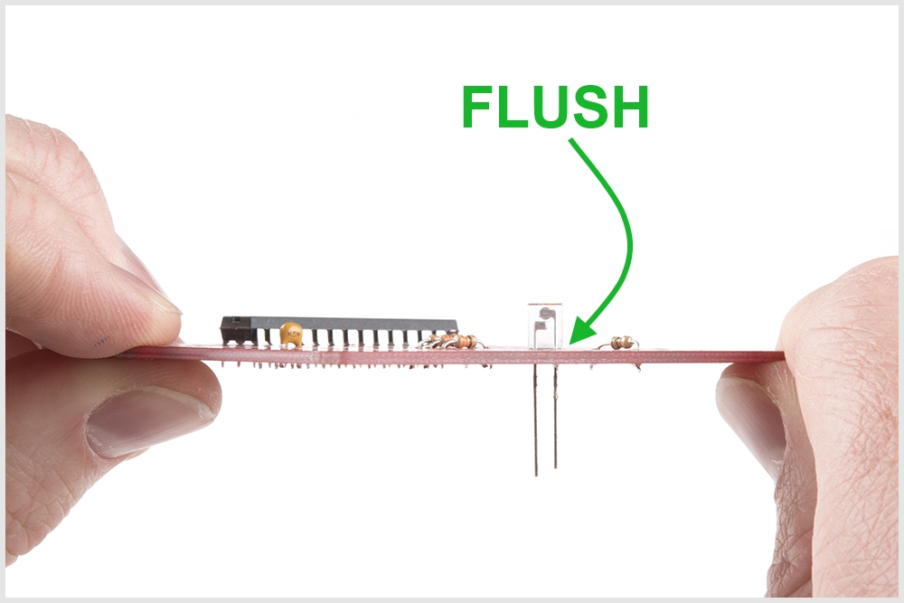
Also ensure that they are flush to the PCB:
When you're done soldering all 6 into place, your PCB should look like this:
To learn more about how IR emitters and detectors work, check out this video: SparkFun Infrared Sensor Overview
Buzzer and Switches
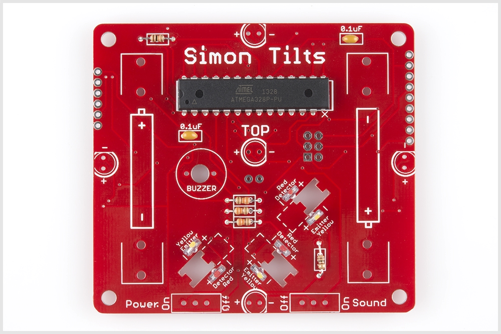
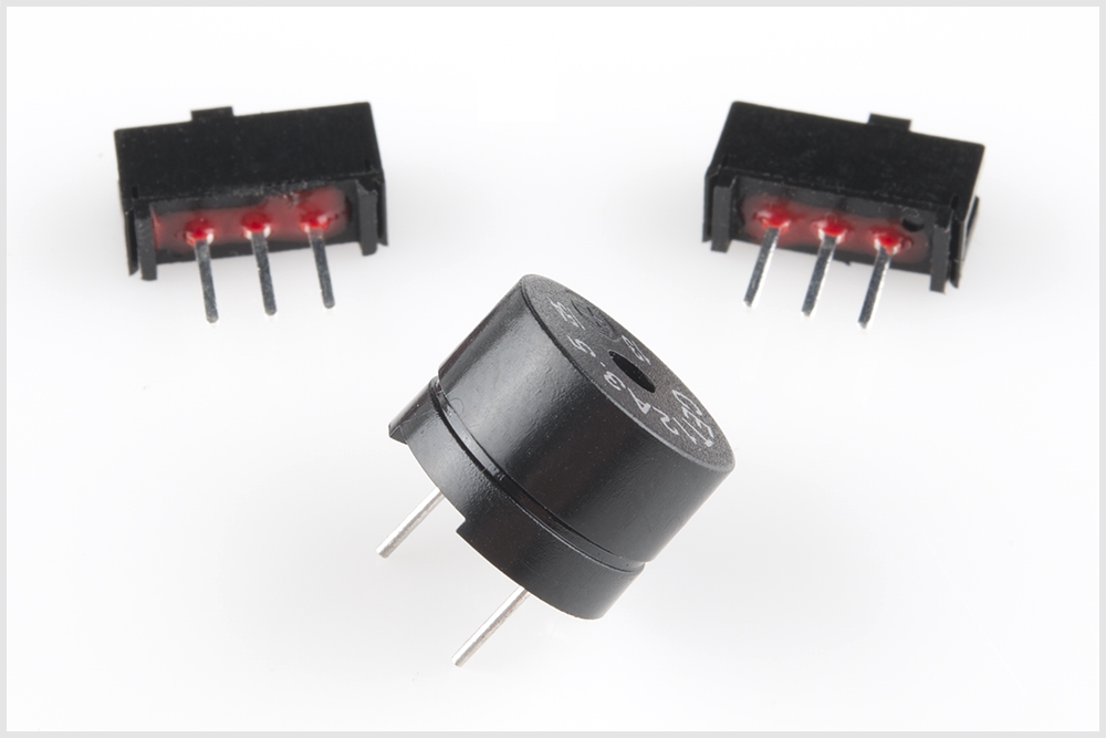
Locate the buzzer and slide switches:
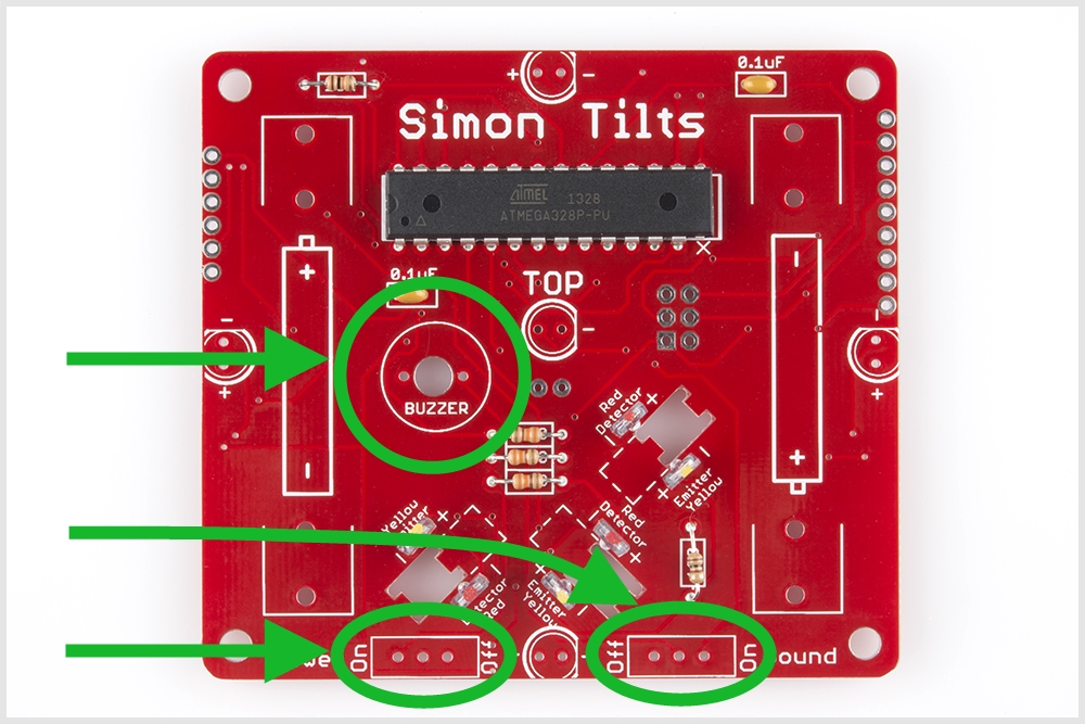
Locate the positions on the PCB:
Place your components in the PCB. Flip it over and solder into place. When you are done, you're PCB should look like this:

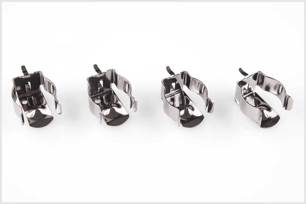
Battery Clips
Locate the 4 Battery Clips:
Locate the 4 positions on the PCB:

Note, these parts must be soldered in so the back sides are facing out. If placed incorrectly, the batteries will not fit. Ensure they are flush and that the back sides are facing out:

Solder into place. When you are done, your board should look like this:
6 Leds
Careful, these next 6 parts are polarized and need to be placed into the PCB properly. To learn more about polarization, please check out this other tutorial: Diode and LED Polarity
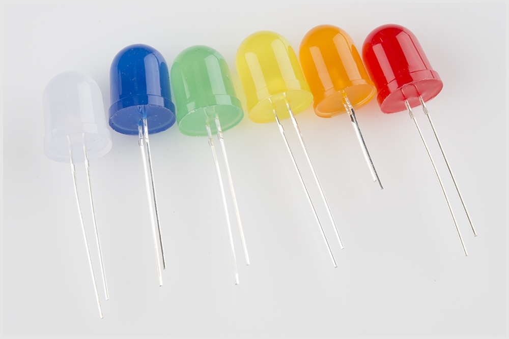
Locate the 6 LEDs. There should be one of each color:
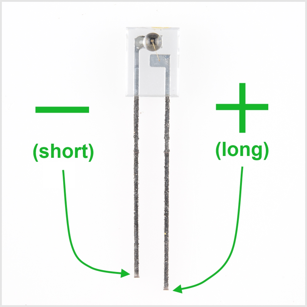
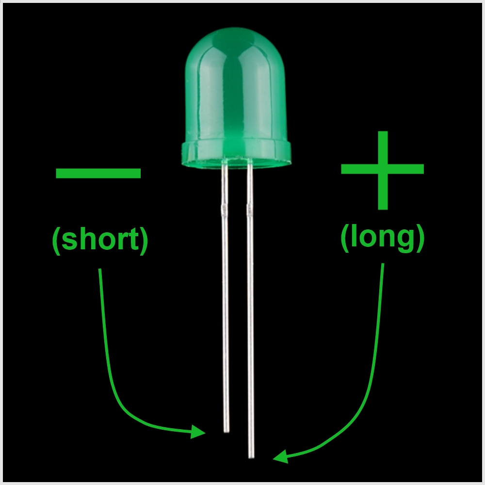
LEDs are polarized. This means there are "-" and "+" legs. Similar to the IR emitter and detectors, the LEDs have difference length legs to show polarity:
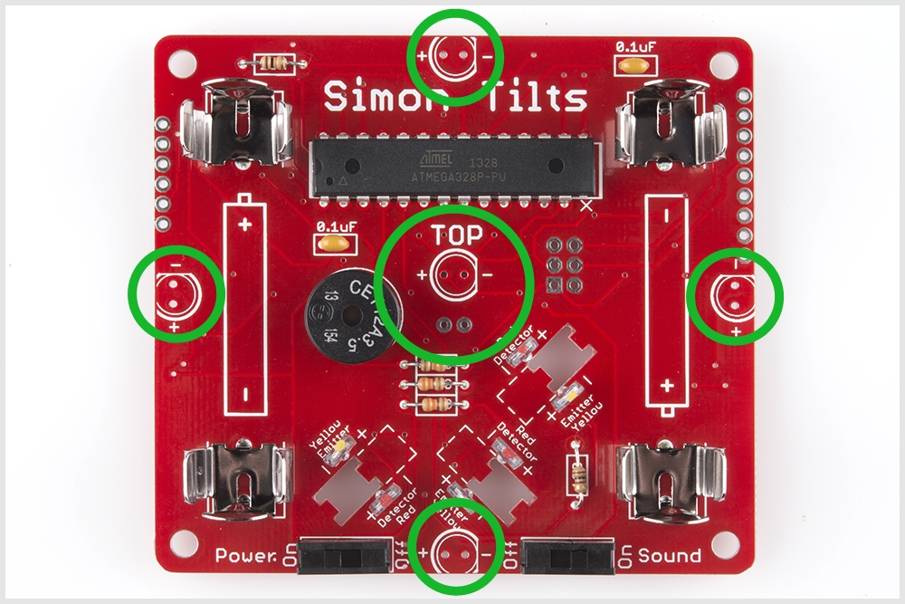
Locate the 6 LED positions on the PCB.
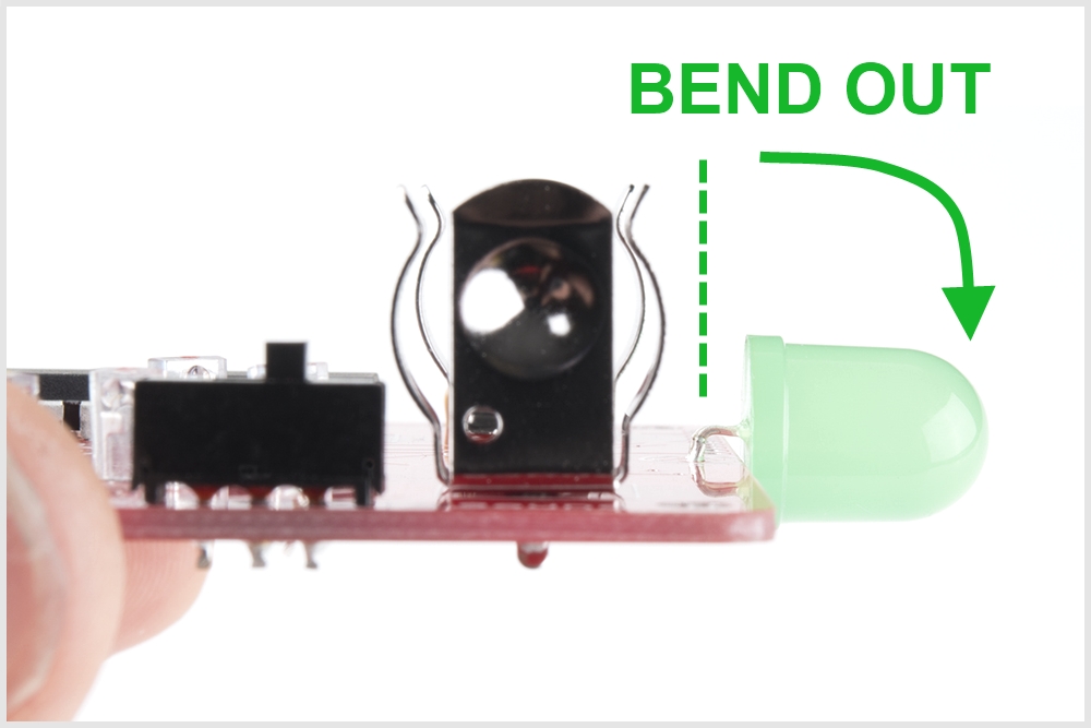
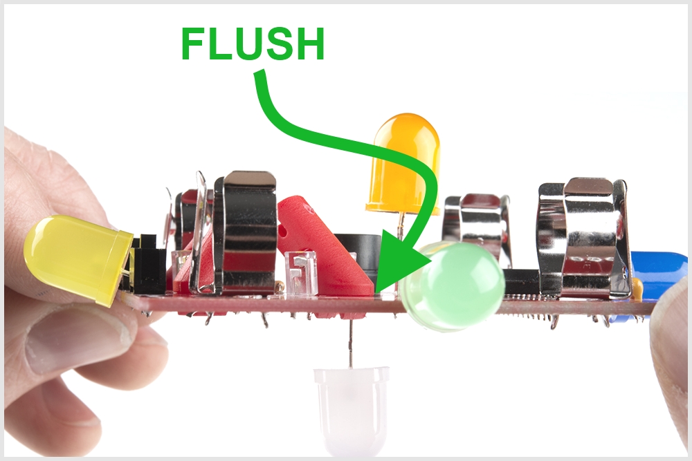
When soldering the outside LEDs, do not solder them flush to the board. Leave a 1/4" inch gap:
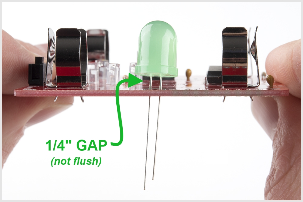
This will enable you to bend the LEDs outward like so:
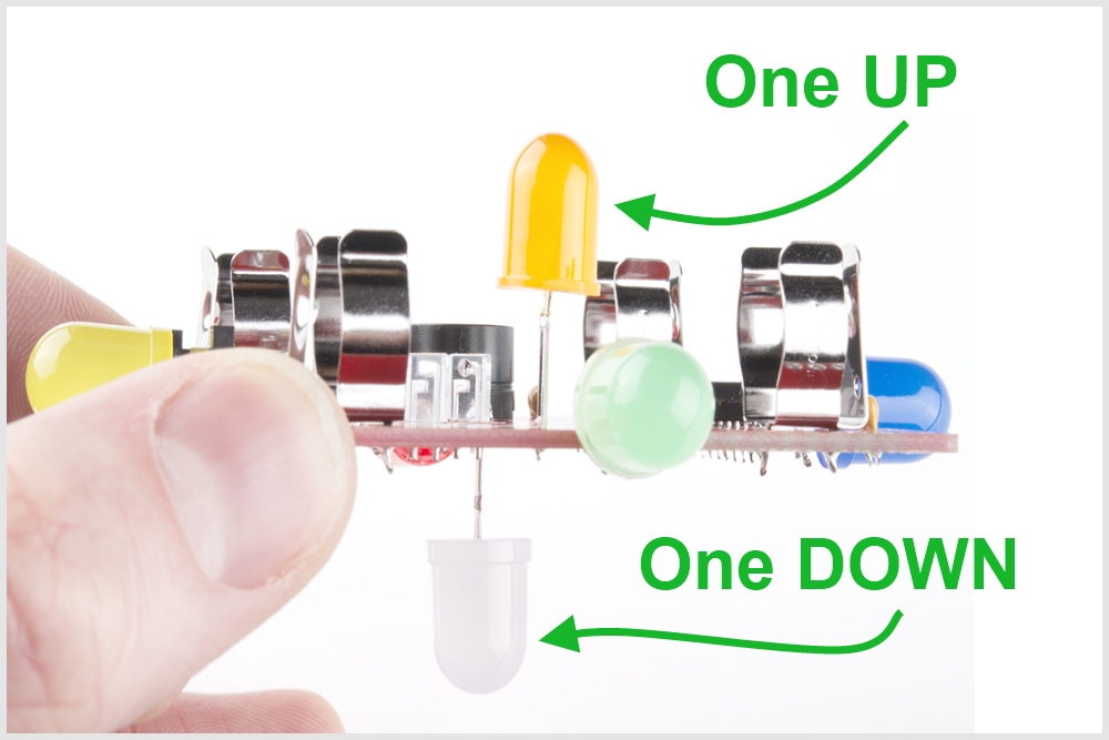
When you solder in the two center LEDs, make sure that one of them goes up, and one goes down:
If you soldered in an LED backwards by mistake, have no fear. Visit the Troubleshooting LEDs section to find out how to easily correct it.
Congratulations! You have completed the soldering portion of assembly. You're almost done!
Cleaning
Before we move on to the final assembly steps, this is a good time to clean your board. Note, this is not absolutely necessary; your Simon Tilts will most likely work even without cleaning. We suggest cleaning it to avoid getting flux on your fingers during game play.
To clean your Simon Tilts, first ensure that you do not have the batteries installed.
You can clean your board using an old toothbrush and some DI water or alcohol.
If you have compressed air, this is a quick way to blow off any liquid. If not, then a paper towel or tissue paper can do the trick.
If you'd like to learn more about cleaning, please check out this tutorial: Electronics Assembly - Washing
Tilt Arms
The last step is assembling and mounting your three tilt arms.
First, find the three red tilt arms:
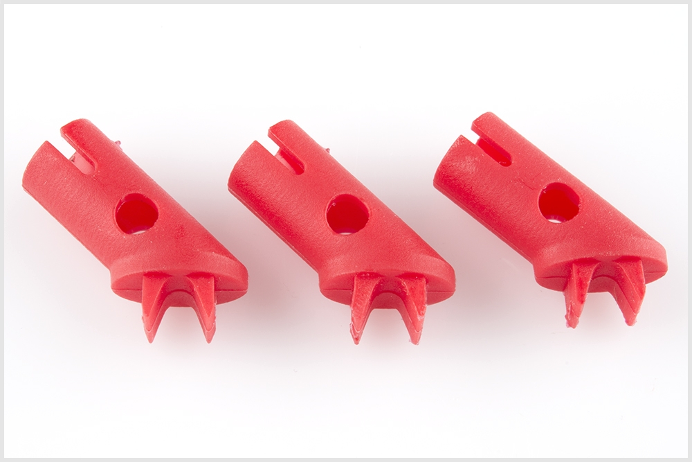
Next, "pop" a BB into each one:
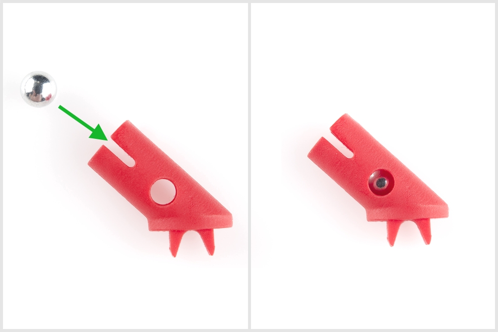
Locate the tilt arm positions on the PCB. Note, there are dashed lines indicating the outline of the tilt arm. This shows you which direction the tilt arm should face:
When you snap them into place, ensure that they are flush with the PCB:
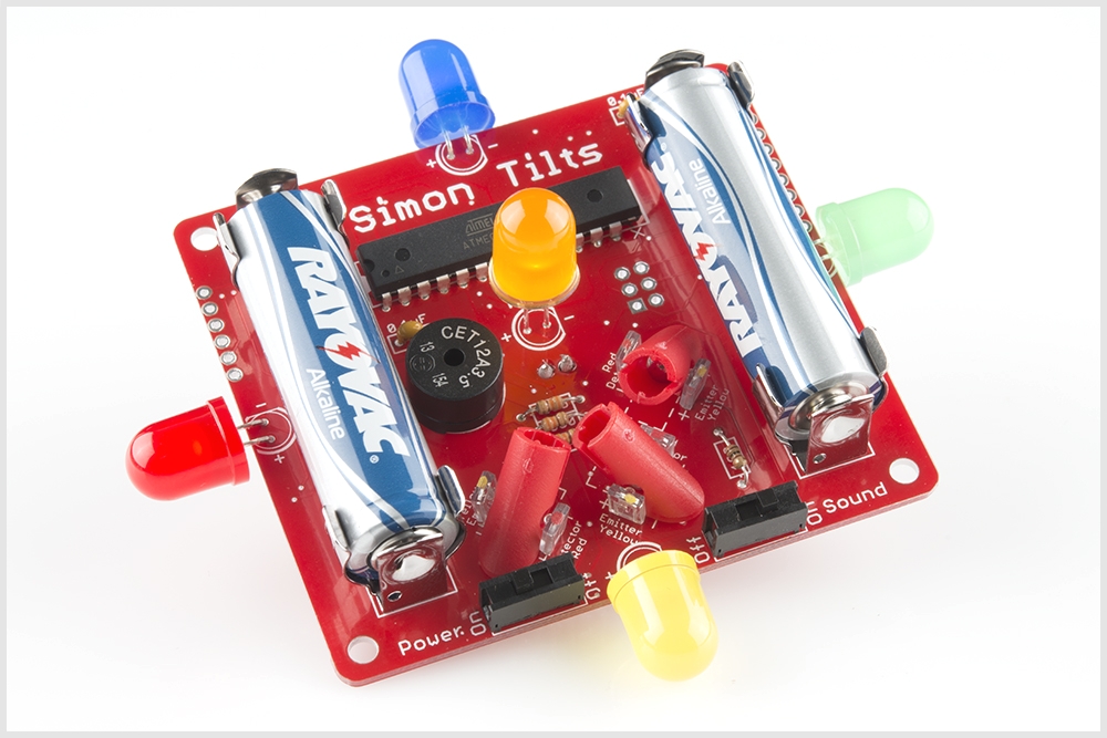
With all three in place, it should look like this:

You're very close now! Just snap the batteries in and turn it on! Ensure you correctly align the "+" and "-" sides of each battery:
How to Play the Game
Before you begin playing with your Simon Tilts, it is important to understand this one major concept:
Simon Tilts is essentially the same game as Simon Says, except for one major difference: each time you rotate a particular LED upward, it is the equivalent of pressing the colored button on the Simon Says classic.
How to Play
Turn it on and watch a pattern of LEDs blink. When it begins cycling through each LED in a fast pattern, it is in "waiting mode". It is now waiting for you to tilt the game in any direction. This is similar to how, in Simon Says, the game will wait for you to press a button to begin.
In order to start a new game, tilt the board in any direction. Then hold it upright and wait for the game to begin.
Simon Tilts will then blink a single LED.
You must now rotate the board so that specific LED is facing upward. After you correctly rotate the first step, then that LED will blink, and you must then go back to the upright position.
Simon Tilts will then repeat the first LED, but then it will also blink a second LED.
At this point, you must rotate each of those two LEDs upward in the correct order. (Note, if you're too slow, then you lose and it will go back into "waiting mode").
After you have completed each recent pattern, your Simon Tilts will blink the same pattern again -- plus one more. The pattern gets longer and longer until you win each level!
- Level 1: 5 steps, slow playback
- Level 2: 10 steps, fast playback
- Level 3 and above: Adds 5 more steps at each higher level, so essentially it goes to INFINITY!!
All six positions are possible - even upside down. It can get pretty tricky when you get into a couple of full rotations :) In addition to the LEDs blinking the pattern, the buzzer makes a unique tone for each position to help you remember the pattern.
Have fun and good luck!
Nightlight Mode
Simon Tilts is much more than just a pattern game. The microcontroller can be re-programmed to be used in many other projects.
As an example, we have included a "secret" mode, called, "Nightlight Mode". In this mode, Simon Tilts does not play a game at all. It simply fades slowly in and out of each LED. A nice way to gently illuminate any room.
To enter Nightlight mode, follow these three steps:
1) Turn it OFF.
2) Hold it upside down.
3) While continuing to hold it upside down, turn it back ON.
Happy glowing and sweet dreams!
Troubleshooting LEDs
Failing LEDs? Don’t fret, there is an easy way to fix it! The most common cause of a failing LED is incorrect polarity. We have designed a special trick into the Simon Tilts PCB. You can simply cut the two traces and close two jumpers. This will swap the polarity without having to remove the LED.
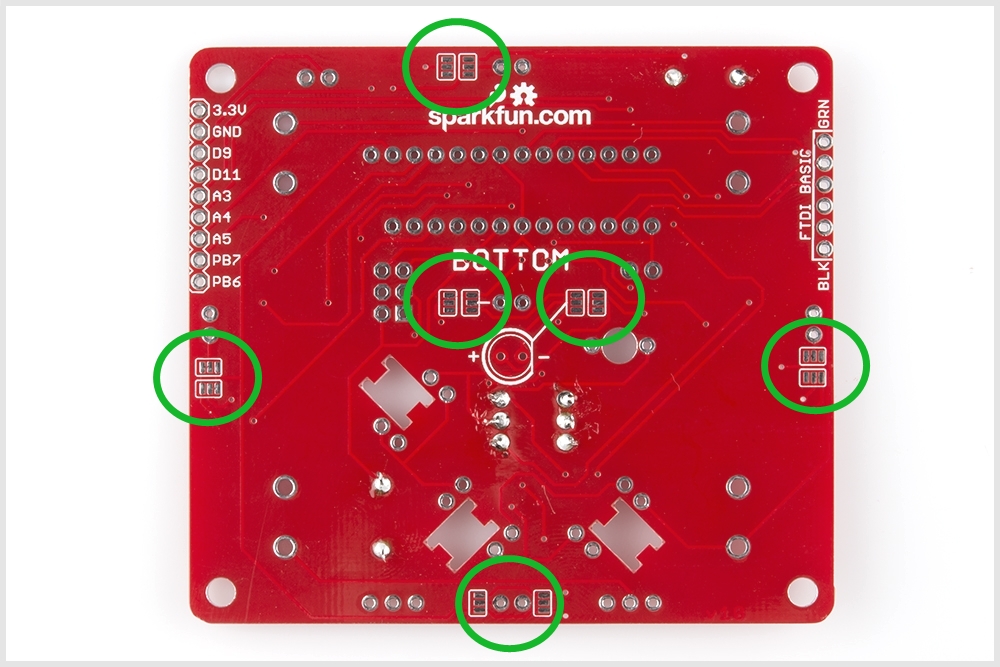
First, find the solder jumpers next to the LED you are trouble-shooting. There are two jumpers per LED. They are located on the bottom side of the PCB, near each LED.
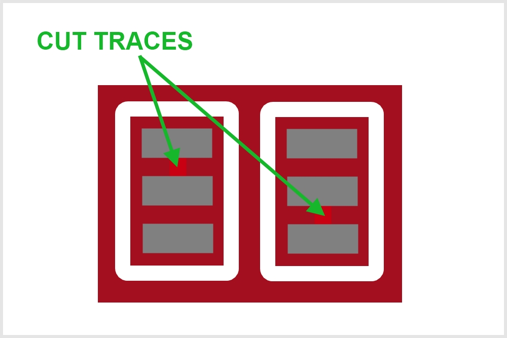
Each jumper has a small trace connecting the middle pad to the default polarity setting. The small trace is sometimes difficult to see, but it is a thin stripe of metal that should show up as a lighter color red. Using a hobby knife (aka x-acto knife), cut the default traces:
Using your soldering iron, close a jumper between the middle pad and the other outside pad:
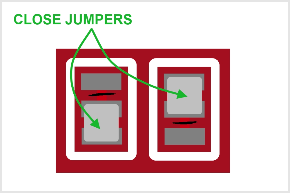
The polarity of the traces running to that LED should now be swapped, and your LED should be lighting up.
Prototyping the Tilt Arm Sensors
Pictured below is one of our early prototypes for the Simon Tilts design. As you can see with all of the hand wiring, sometimes it takes more than a few tries to find the best solution.

You can see two of our initial approaches to sensing the tilt position. The first one you may notice is the three tilt sensors:

In this approach, we are using our Tilt Sensors.
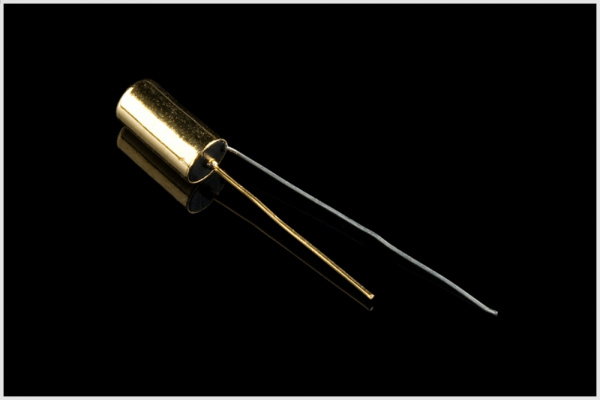
Each of these has a little metal ball inside that closes or opens a switch between the two leads. In this way of using a falling ball within a cylinder, it is very similar to our final Tilt Arm approach. The only difference is that the standard tilt sensor was not reliable enough for our application. We were getting very inconsistent readings from each sensor. Plus, the legs of those tilt sensors are pretty thin wire, and so after a little fumbling around, they would bend out of position.
The second approach that you can see in the above prototype is using hall effect sensors, magnets and white plastic tubes. This method actually proved to be very reliable and consistent. The only downside was that it was much more expensive and would require sourcing tubing and/or getting a custom molded cylinder part made.
Both of these approaches had one more down side: they required the user to precisely bend the sensor to a 45 degree angle. We found that if this angle was just slightly off, then the sensor would begin malfunctioning. So we continued to brainstorm for a solution that would avoid this problem.
With another prototype we used out Tilt-a-Whirl Breakout - RPI-1031.
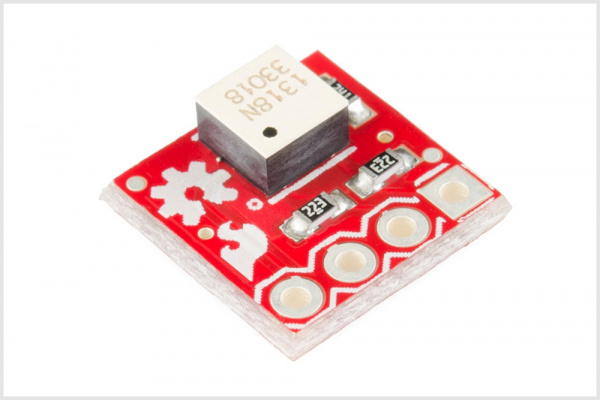
It worked pretty well, but we wanted to keep this design 100% PTH parts. Also, it required two of them, which would add to the cost. Also, (just like the other tilt solutions, they had to be positioned at a 45 degree angle, which meant bending headers or tricky soldering.
During all of our prototyping, the accelerometer BOB was actually an option in the back of our minds. Our Triple Axis Accelerometer Breakout - MMA8452Q would work well for this application.
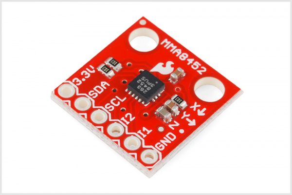
There was one problem with using a breakout board: the sensor itself is not a PTH part. Although we could include a footprint on the PCB to mate with the accelerometer's pinout, we were hesitant to use this approach. Adding one more "black box" to the project can increase the barrier to understanding a technology for a newbie.
Ultimately, we opted to create our own unique custom molded part:
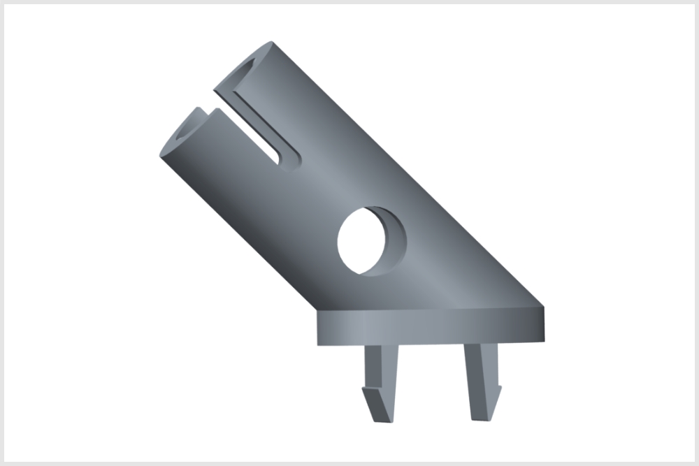
It uses an IR emmitter and detector in order to know the position of the BB ball inside the cylinder. The IR emitter and detector are positioned so that the IR beam "shoots" through the hole in the bottom of the cylinder. When the BB is resting at the bottom of the cylander, then it is blocking the IR beam. When the BB is resting at the upper end of the tilt arm, then the "look-through" hole is unobstructed, and the IR detector can sense the emitter.
In order to make using this part easier, we created a device in our Eagle Library:
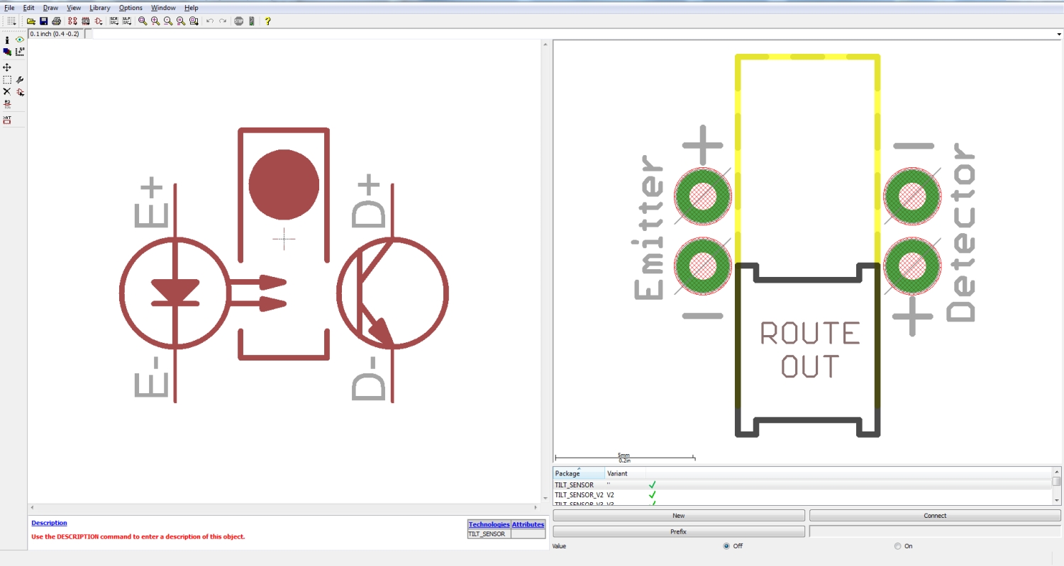
The package includes the correct positioning of the emittor, detector and dimension route out area to mate with the tilt arm part. An important thing to note is that when choosing a pull-up resistor for the detector line, we found that 330 ohms was the best value. This value is used in the kit. We first tried using the internal pullups on the ATmega328, but the voltage swing from the detector was very minimal which made it hard to get accurate readings.
We'd like to send a huge thank you to Modrobotics, because they printed three rounds of prototypes for us!
We'd also like to thank Mountain Molding for all their help with design, tooling, and manufacturing the part!
Resources and Going Further
If you'd like to further understand how the Simon Tilts design works, a good place to start is looking at the design files.
For more information, check out the resources below:
- Schematic (PDF)
- Eagle Files (ZIP)
- SparkFun Blog Post: Creating a Custom Tilt Sensor
- Simon Tilts GitHub Repository
- Product Demo Video
Reprogramming Simon Tilts
Your Simon Tilts game is re-programmable with Arduino. This means that you can change the rules of the game, add more features, or turn it into a completely different project. For more information about how to re-program using Arduino, check out these tutorials tutorial:
What is an Arduino?
Installing Arduino IDE
If you're interested to learn more about writing code, a good place to start is by completing the example circuits in the SparkFun Inventors Kit.
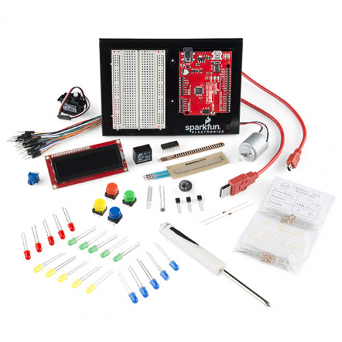
The microcontroller included with your Simon Tilts is actually re-programable with Arduino. This is the same microcontroller that is used in the RedBoard SIK. This means that if you wanted to, you could use the skills learned in the SIK to modify your Simon Tilts. For example, you could change the way the game plays or use it for an entirely different project!
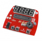
More Kits!!!
If it's more soldering that you're after, here are a few suggestions for other fun PTH soldering kits:
To see all of the kits we offer on our website, checkout our Kits Category on the SparkFun website.