Haptic Motor Driver Hook-Up Guide
 LightningHawk
 Introducing the Haptic Motor Driver
Ready to add some good vibes to your project? Look no further than the Haptic Motor Driver. This board breaks out Texas Instruments' DRV2605L haptic motor driver, which has some seriously cool features. Add meaningful feedback from your devices using the Haptic Motor Driver and an Arduino compatible device. This tutorial will get you up and running, or vibing, in no time with the I2C library for Arduino and example projects that give you the hardware setup and the code for various modes of operation.
Features
- Flexible Haptic and Vibration Driver for both ERM and LRA type motors
- I2C Controlled Digital Playback Engine
- Audio to Vibe
- PWM input with 0% to 100% Duty-Cycle Control Range
- Hardware Trigger Input
- Built-in Waveform Sequencer and Trigger
And that is just to name a few. See the DRV2605L datasheet for a complete list.
Required Materials
You'll need a handful of extra parts to get the Haptic Motor Driver up-and-running. Below are the basic components used in this tutorial, if you want to follow along.


SparkFun Cerberus USB Cable - 6ft
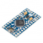
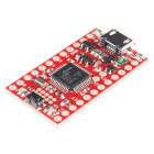
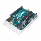
CAB-12016A microcontroller that supports I2C is required to communicate with the DRV2605L and relay the data to the user by means of vibration. The SparkFun RedBoard or Arduino Uno are popular options for this role, but just about any microcontroller development board should work. (The firmware examples use an Arduino library, if that serves as any extra motivation to use an Arduino.)
Suggested Reading
The DRV2605L is designed for a handful of uses. The Technical Documents provided by Texas Instruments includes application notes, user guides, literature and blogs. The DRV2605L communicates over I2C. We’ve got a great library to make it easy to use. We’re going to be using a breadboard to connect the breakout board to the RedBoard. If these subjects sound foreign to you consider browsing through these tutorials before continuing on.
How to Solder: Through-Hole Soldering
Installing an Arduino Library
How to Use a Breadboard
I2C
Hardware Overview
Parametrics
| Parameter | Description |
|---|---|
| Min-Max Source Voltage | 2V - 5.2V. |
| Special Features | Integrated Haptic Effects & Smart Loop Architecture. |
| Input Signal | PWM, Analog, I2C. |
| Maximum Output Voltage | 10.4V. |
| Haptic Actuator Type | ERM & LRA type motors only. |
| Shut Down Current | 4uA. |
| Quiescent Current | 0.5mA - Important for your battery powered projects. |
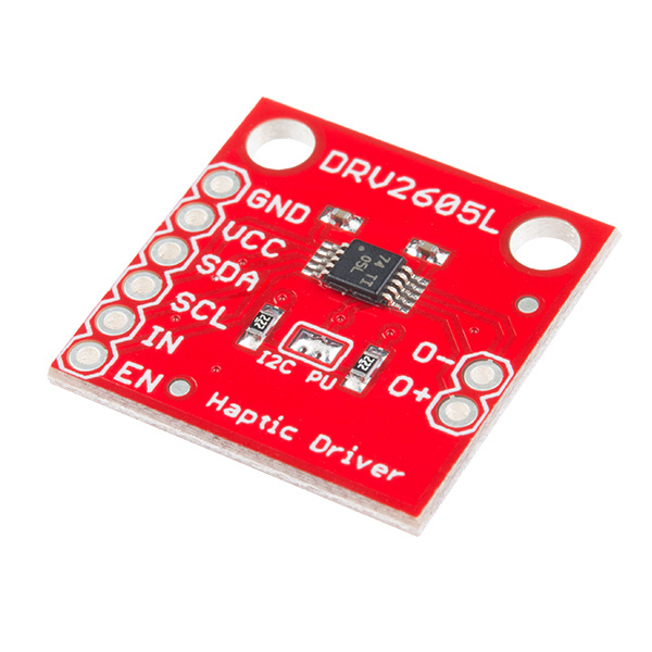
Pin Descriptions
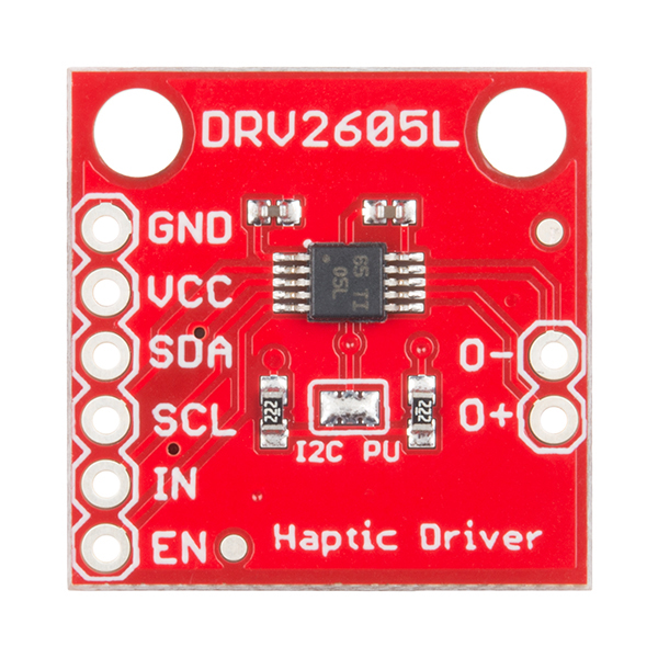
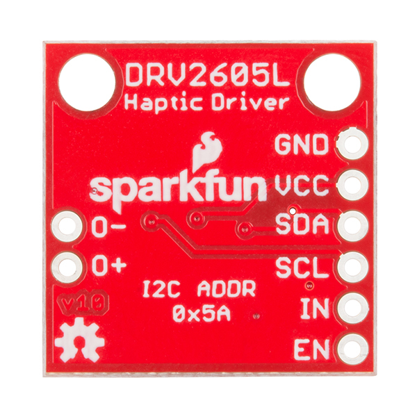
The SparkFun Haptic Motor Driver - DRV2605L breakout board provides 6 pins to provide power to the sensor and I2C bus.
| Pin Label | Description |
|---|---|
| GND | Connect to ground. |
| VCC | Used to power the DRV2605L Haptic Motor Driver. Must be between 2.0 - 5.2V |
| SDA | I2C data |
| SCL | I2C clock |
| IN | Analog and PWM signal input |
| EN | Enable pin. Connect to VCC for most applications. |
| O- | Negative motor terminal. |
| O+ | Positive motor terminal. |
Setting the Jumpers
On the front of the breakout board is a solder jumper:
- I2C PU -- This is a 3-way solder jumper that is used to connect and disconnect the I2C pullup resistors. By default, this jumper is closed, which means that both SDA and SCL lines have connected pullup resistors on the breakout board. Use some solder wick to open the jumper if you do not need the pullup resistors (e.g. you have pullup resistors that are located on the I2C bus somewhere else).
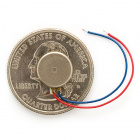
ERM and LRA Motors
The DRV2605L is capable to driving two different types of motors. So what are they? How do they work? How are they different?
Precision Microdrives published application notes on using both Eccentric Rotating Mass, ERM and Linear Resonant Actuator, LRA type motors. The default firmware for the DRV2605L is set for use with ERM type motors. There are six effects libraries for the ERM type and only one for LRA.
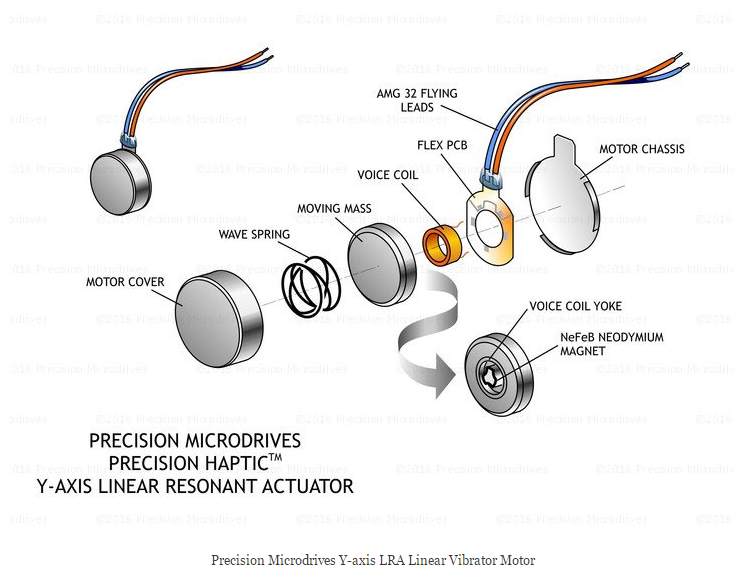
The difference between the two motors is how the movement of a mass is displaced. LRA vibration motors require an AC signal, driving a sine waveform that is modulated to get multiple effects. ERM vibration motors use a DC motor with a counter weight attached. The DC voltage controls the speed of the motor.
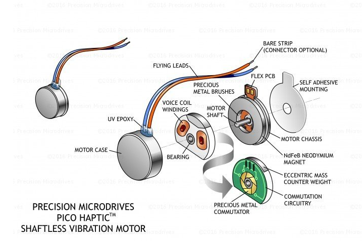
The ERM has an off-centre load, when it rotates the centripetal force causes the motor to move. The rotation is created by applying a current to the armature windings attached to the motor shaft. As these are inside a magnetic field created by the permanent magnets on the inside of the motor’s body, a force is created causing the shaft to rotate. To ensure the rotation continues in the same direction, the current in the windings is reversed. This is achieved by using static metal brushes at the motor terminals, which connect to a commutator that rotates with the shaft and windings. The different segments of the commutator connect to the brushes during rotation and the current is reversed, maintaining the direction of rotation.
In a similar method, LRAs use magnetic fields and electrical currents to create a force. One major difference is the voice coil (equivalent of the armature windings) remains stationary and the magnetic mass moves instead. The mass is also attached to a spring, which helps it return to the centre. Driving the magnetic mass up and down causes the displacement of the LRA and thereby the vibration force.1
More Suggested Reading
- ERM Vibration Motors
- LRA Vibration Motors
- Haptics
- Solutions for Haptics
- How Devices Provide Haptic Feedback
1: "AB-020 : UNDERSTANDING LINEAR RESONANT ACTUATOR CHARACTERISTICS." Application Note. Https://www.precisionmicrodrives.com. N.p., n.d. Web. 29 Nov. 2016.
Using the SparFun DRV2605L Library
To use the SparkFun Haptic Motor Driver, you will need some supporting software. If you use Arduino, then you are in luck! We created an Arduino Library that makes the DRV2605L easy to use. To automatically install the library from the Arduino IDE simply navigate to Sketch > Include Library > Manage Libraries... and search for SparkFun Haptic Motor Driver. Or you can grap the zip here from the GitHub repository to manually install:
The SparkFun DRV2605L library has every register defined, and simple functions can be called to create a custom haptic experience. Every register must be set (or use the default if that works for you). Use the datasheet to help you with the values that need to be written to the registers.
Going through the library header file, you'll see just about every register has a comment with its function and corresponding page number in the data sheet. This board is capable of operating in seven modes and can use either an LRA or ERM type motors. We will explore 2 of the modes -- Internal Trigger mode, and PWM mode. From here it shouldn't take much to get the device working in other modes.
Let's explore each example in detail.
Internal Trigger Mode
The internal trigger mode allows you to play a waveform or a custom waveform sequence from the ROM waveform memory. In this example we will play all 123 waveform effects by loading them in all eight waveform sequencer registers. This simple sketch will also help you become familiar with the effects library so you can start to build your own custom effects sequences. See page 60 of the datasheet for the full list of waveform effects. Each library -- listed on page 14 of the datasheet -- has its own rated voltage, rise-time and brake-time.
Parts Needed

Hardware Connection
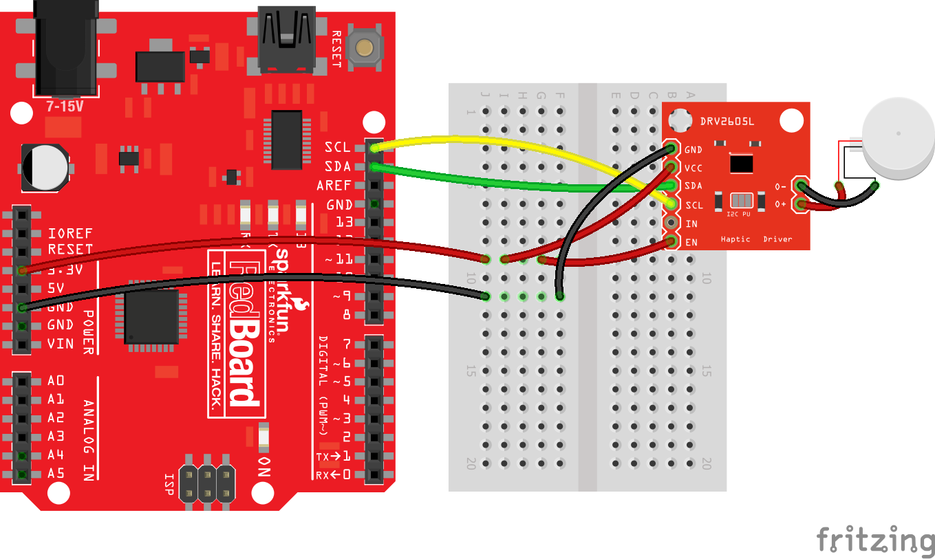
The hardware consists of the standard I2C connection and the enable (EN) pin must be pulled high.
Arduino Program
language:c
#include <Sparkfun_DRV2605L.h> //SparkFun Haptic Motor Driver Library
#include <Wire.h> //I2C library

SFE_HMD_DRV2605L HMD; //Create haptic motor driver object

void setup()
{
  HMD.begin();
  Serial.begin(9600);
  HMD.Mode(0); // Internal trigger input mode -- Must use the GO() function to trigger playback.
  HMD.MotorSelect(0x36); // ERM motor, 4x Braking, Medium loop gain, 1.365x back EMF gain
  HMD.Library(2); //1-5 & 7 for ERM motors, 6 for LRA motors

}
void loop()
{
  int seq = 0; //There are 8 sequence registers that can queue up to 8 waveforms
  for(int wave = 1; wave <=123; wave++) //There are 123 waveform effects
  {
     HMD.Waveform(seq, wave);
     HMD.go();
     delay(600); //give enough time to play effect
     Serial.print("Waveform Sequence:      ");
     Serial.println(seq);
     Serial.print("Effect No.:      ");
     Serial.println(wave);

    if (wave%8==0) //Each Waveform register can queue 8 effects
    {
        seq=seq+1;
    }
    if (wave%64==0) // After the last register is used start over
    {
        seq=0;
    }
  }
 }
PWM & Analog Input Mode Example: Light Vibes
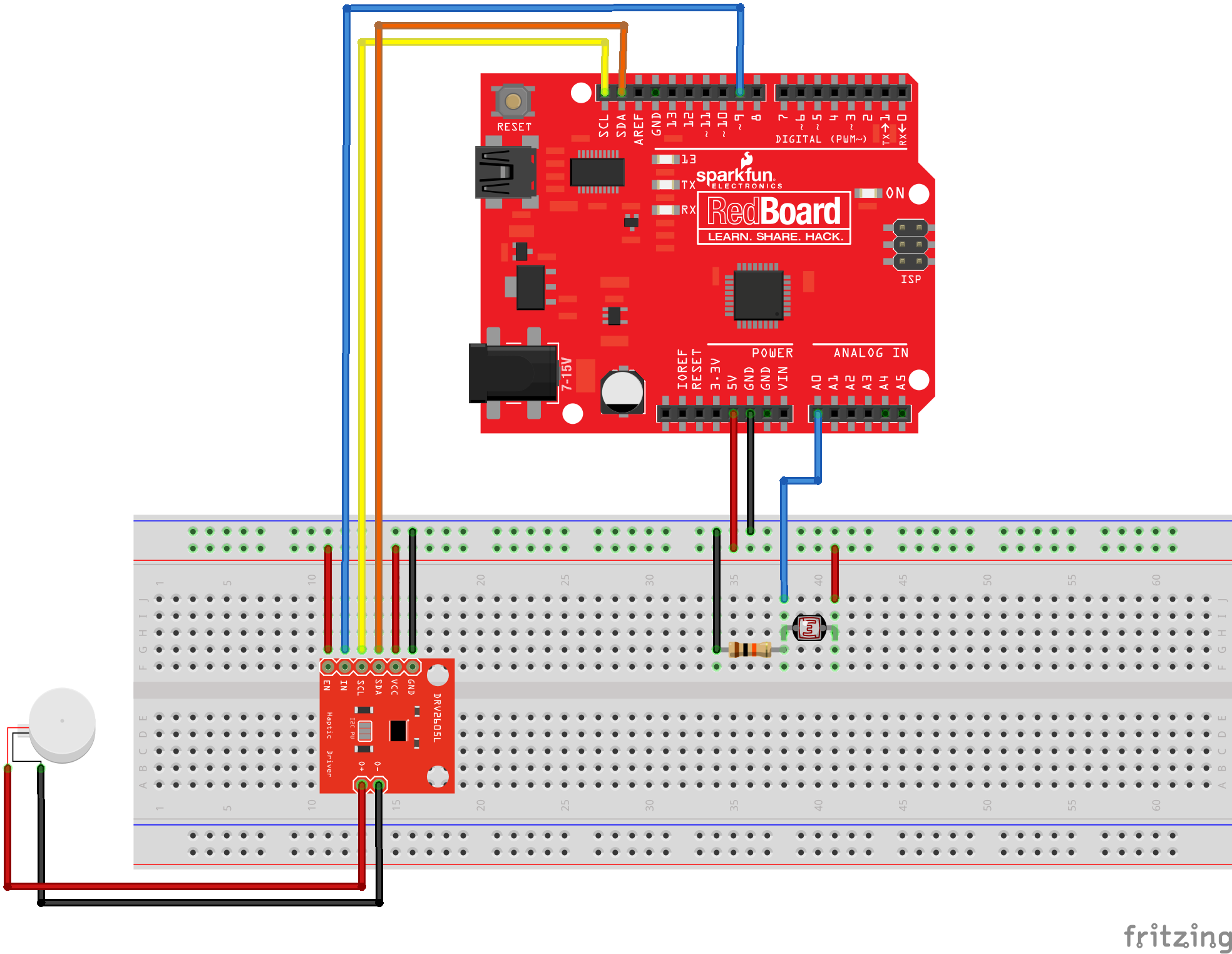
In this example project, we are going to control an ERM motor based on analog input from a photocell that gets mapped to a range from 0-255 and uses that result to set the pulse width modulation of an output pin connected to the IN/TRIG pin on the Haptic Motor Driver. This project will give haptic effects based on the amount of ambient light in an area.
Waving your hand over the photoresistor turns off the motor, and, when you move your hand away, you can feel the ramping effects as the PWM signal increases with the amount of light detected.
Parts Needed
In addition to the basics like hook-up wire, you'll also need the following parts:
The Circuit
Arduino Sketch
language:c
// Control the vibration of an ERM motor
// using PWM and a photoresistor.

#include <Sparkfun_DRV2605L.h>
#include <Wire.h>

SFE_HMD_DRV2605L HMD;
const int analogInPin = A0;  // Analog input pin that the sensor is attached to
const int analogOutPin = 9; // Analog output pin that the Haptic Motor Driver is attached to

int sensorValue = 0;        // value read from the sensor
int outputValue = 0;        // value output to the PWM (analog out)


void setup()
{
  HMD.begin();
  Serial.begin(9600);
  HMD.Mode(0x03); //PWM INPUT
  HMD.MotorSelect(0x0A);
  HMD.Library(7); //change to 6 for LRA motors

}
void loop()
{

 // read the analog in value:
  sensorValue = analogRead(analogInPin);
  // map it to the range of the analog out:
  outputValue = map(sensorValue, 0, 1023, 0, 255);
  // change the analog out value:
  analogWrite(analogOutPin, outputValue);

  // print the results to the serial monitor:
  Serial.print("sensor = ");
  Serial.print(sensorValue);
  Serial.print("\t output = ");
  Serial.println(outputValue);

  // wait 2 milliseconds before the next loop
  // for the analog-to-digital converter to settle
  // after the last reading:
  delay(2);
 }
Resources and Going Further
Now that you have been through three of modes of operation, try out the other four and use an LRA motor! How will you add haptics to your next project?
Here are are the numerous resources and documents mentioned through out this tutorial.
For more motor-related fun, check out these other great SparkFun tutorials: