Build a Qwiic Jukebox that is Toddler Approved!
 QCPete
 Introduction
In this tutorial, we will guide you through how to make your very own jukebox. This project is intended to be used for toddlers, but can also serve as a great learning tool for any future audio or RFID projects. It is Qwiic-based, and so does not require soldering. For an overview of the project, please check out the following video:
Required Materials
To follow along with this tutorial, you will need the following materials. You may not need everything though depending on what you have. Add it to your cart, read through the guide, and adjust the cart as necessary.
Tools
Wiring up the electronics actually requires no tools at all, but depending on what you decide to do for your enclosure, you may need some general crafting tools. These could include scissors, hobby knife, Velcro tape, Scotch tape, and hot glue.
Although in this tutorial we will be showing a custom enclosure (with bent acrylic and a faceplate), the jukebox could very easily be housed in a cardboard box.
Suggested Reading
You are more than welcome to jump right into this project and learn from the code provided here, but if you'd like to do some reading and/or prototyping ahead of time, it couldn't hurt to check out the products involved and their individual hookup guides. Also, if this is your first time working with Arduino, we highly recommend checking out the Installing Arduino IDE to get you up and running.
Installing Arduino IDE
Button and Switch Basics
RedBoard Qwiic Hookup Guide
SparkFun Qwiic RFID-IDXXLA Hookup Guide
Hardware Overview
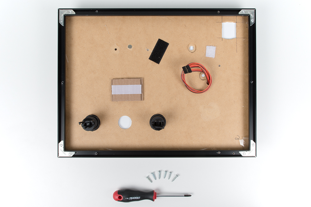
Since, this system only uses Qwiic boards, it's really quite simple to plug everything together. The pictures below, show how everything should be plugged in. The RedBoard Qwiic, MP3 trigger, and RFID reader all have Qwiic connectors (the small black connectors with four pins) for a solderless project. The buttons will require a bit more of precision (plugging into the correct pins on the RedBoard Qwiic), but we will go into that with more detail in the next section.
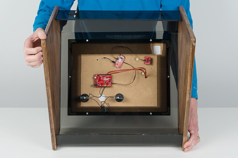
Back of project enclosure. (Click to enlarge.)

Hardward connections. (Click to enlarge.)
The Qwiic connectors and cables are polarized, so you don't have to worry about plugging in a cable backwards. The Qwiic boards can also be plugged in any order, they just need to daisy-chained together. This is handy as you may want a different order of connections depending on how your enclosure and faceplate are setup.
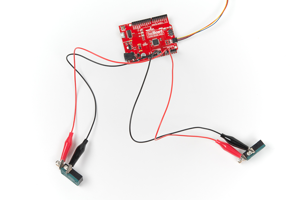
Buttons
The buttons need to be wired up to specific pins on the Arduino. These arcade buttons are actually made up of two parts. There is the large mechanical button that you press and then there is the electrical switch, which can be removed.
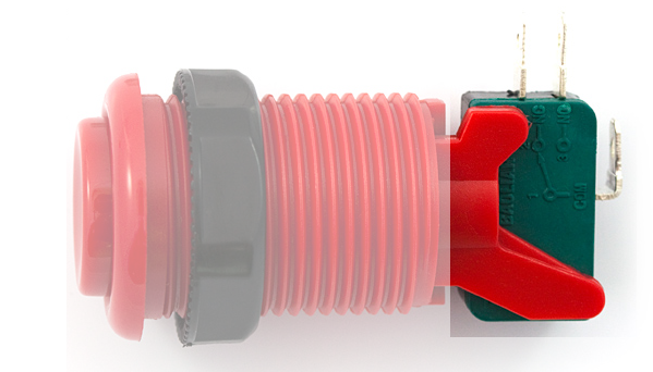
Button assembly. (Click to enlarge)
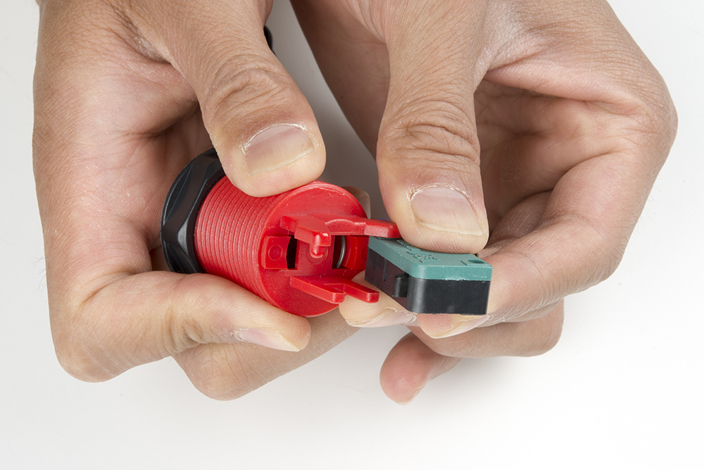
Removing switch from assembly. (Click to enlarge)
Above you can see the electrical switch removed from the larger housing. We need to connect the buttons to each Arduino pin as listed in the tables below. (COM stands for common and NO stands for normally open.)
Button one (PLAY):
| Button terminals | Arduino pins |
|---|---|
| NO | A0 |
| COM | GND |
Button two (STOP/PAUSE):
| Button terminals | Arduino pins |
|---|---|
| NO | A2 |
| COM | GND |
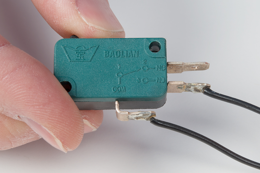
Close up of electrical switch. (Click to enlarge)
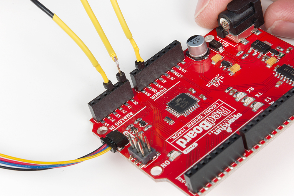
Wiring to RedBoard. (Click to enlarge)
Here, I've got some buttons pre-soldered. They were from a previous project. If you're comfortable soldering, then go ahead and solder it up! If you'd like to create this project without any soldering (and potentially involve the toddler a bit more), it can be done with our alligator to "pig-tail" cables.
You could also pull off this project with a single button, and change the functionality to just PLAY/PAUSE. The current code provided here uses the STOP button for two purposes. A single press of the STOP button will do just that, stop the track. But a double-press of the STOP button will PAUSE the track. Normally, the pause and play functions are tied to the same button, but this was a design choice my toddler made.
Power options
You have two options: Barrel jack or microB USB.
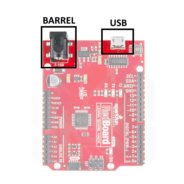
In the wish list above, we have included a USB wall adapter and a USB cable. This is nice because this cable can be used for programming and then also power. If you have a cell phone charger (with USB micro-B type connector), this would work fine too for simply powering after programming.
Speaking of power, the hamburger speaker get's about 3 hours of play time on each charge. If you'd like to avoid having to re-charge, you can leave this permanently plugged into a USB Mini-B type connector and additional USB wall adapter.
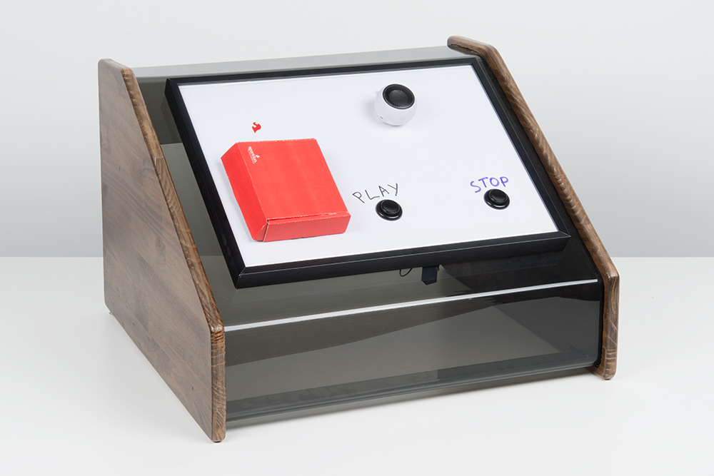
The Enclosure
A lot of my projects end up in some size of a cardboard red box, but for this one, I actually had an enclosure from a previous project sitting in my basement.
Shaping the Acrylic
As I was walking this project into the office, the first thing people asked me was, "Did you bend that acrylic?" Yep. It's actually not as difficult as it may seem. It requires a heating element strip that can be a little pricey. I believe the one we had at SparkFun was something similar to this.
The process is relatively simple, it involves planning your bend points. Then, you lay the acrylic piece on top of the heating element strip for a few minutes and it starts to get soft. If you hear crackling and see bubbles, then you've heated it too long.
I'd be curious if anyone reading has attempted to make their own heating element similar to this (or has any ideas on how to do it DIY). Please comment below. From all of the interest I have seen with this enclosure, I'm sure a cheaper DIY option would be very popular.
The Wooden Frame
For my enclosure, I opted to have wood sides. It makes for a nice finished look (without any screws or bolts showing). I used a hand router to make some channels where the edge of the bend acrylic would "press" into the side of my wood sides. Some great info on hand routing here.
If you had a CNC machinelike the Shapeoko XXL, you could design the route and get a much cleaner cut. To do it by hand, I layed my bent acrylic on it's side (on top of the wood), traced it, then slowly guided the router along the trace.
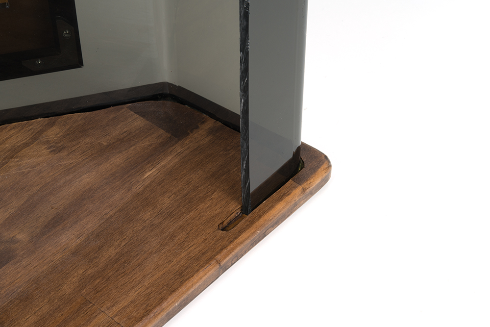
Imperfections on the inner cut. (Click to enlarge.)
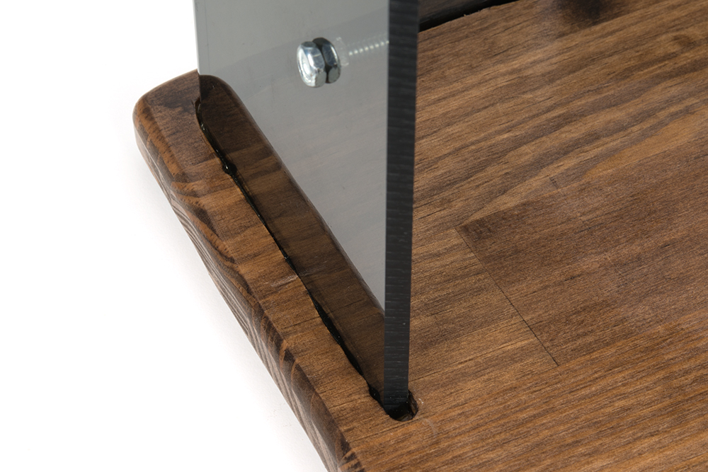
Frame glued with epoxy. (Click to enlarge.)
In the picture on the left, you can see how my route isn't perfectly straight, but ultimately the small imperfections will not be noticed. After a quick stain on the wood and a couple sprays of poly, the final step is to fill the route with a bead of epoxy and slide the acrylic into place (pictured on right).
The Faceplate
I opted to have a removable faceplate, so that I could have better access to the electronics during development and eventually re-purpose this enclosure for various projects. I'm so glad I did, because it worked perfectly for this jukebox project.
Arduino Library
The easiest way to install the required Arduino library is by clicking on the link at the top of the code. This will launch library manager. Then click "install".
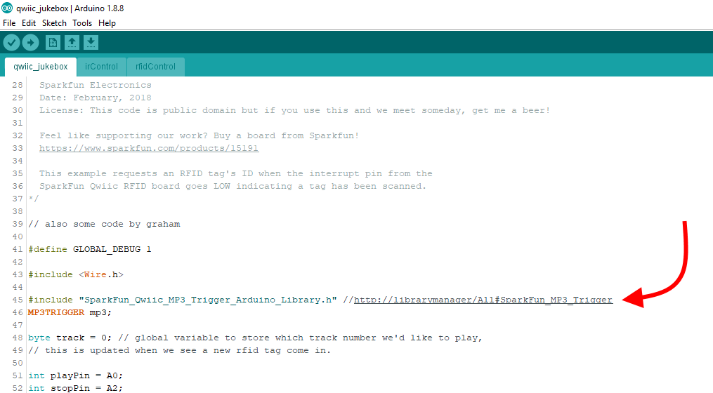
You can also open library manager and search for SparkFun MP3 Trigger. And lastly, to manually install, head on over to the MP3 GitHub repository or feel free to download the library below:
There is no library required for the RFID reader. However, if you would like, you can download the firmware and example files from the Qwiic RFID GitHub repository.
Arduino Code
All of the Arduino code necessary for this project lives in a GitHub repository here:
Once you have your hardware all plugged in, follow these steps to get your jukebox up and running:
- Download the code from the GitHub project repository.
- Install the Arduino Library for Qwiic MP3.
- Upload the project sketches to your RedBoard Qwiic. There should be 3 tabs open in the Arduino IDE; one for each of project sketches.
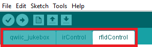 Project file tabs in Arduino IDE.
 - Open a terminal at 115200 bps and listen to debug messages.
- Determine each of your RFID tags' IDs, by holding each tag up to the reader and watching the serial monitor.
- Update the
tagList[]in therfidControl.inosketch.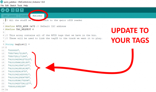
rfidControl.inosketch updated with the RFID tag IDs. (Click to enlarge) - Upload your modified code.
- Prepare your μSD card with the MP3 files.

The bones of this code come from these two examples: Qwiic MP3 Trigger: Example 1 and the Qwiic RFID: Example 1.
The main loop(), in the project sketch, basically does three things:
- Checks for new tags (either from the RFID or the IR crafty card reader). Updates active track if necessary.
- Checks PLAY button. Commands Qwiic MP3 board to play if pressed.
- Checks STOP button. Commands Qwiic MP3 board as necessary. Note, this also waits to see a second "tap" indicating the user wants PAUSE.
Preparing the uSD card
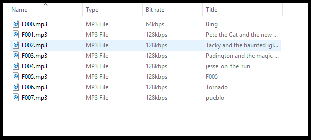
In order for your jukebox to play any songs or audio books, you will need to load up the micro SD card with some MP3 files. The most important thing to do here is name them correctly; the files must be named F000.mp3, F001.mp3, F002.mp3, and so forth. For more info, see our Qwiic MP3 Trigger Hookup Guide.
The tagList[], mentioned in the previous section, is where the RFID tags' IDs are linked to the MP3 files you want to play. This array of strings is located in the rfidControl.ino file, within the GitHub project repository. When using the Arduino IDE, it should be available as a tab (see image above).
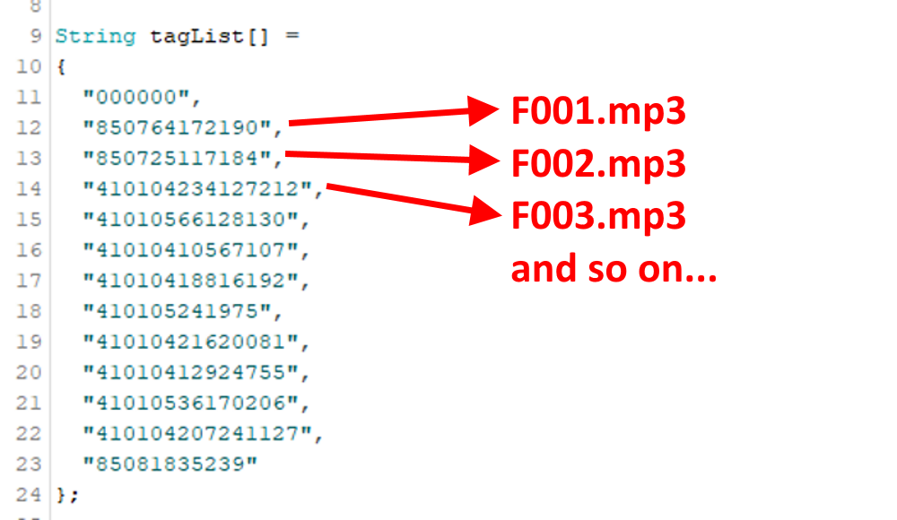
tagList[] string array in the rfidControl.ino file. The first spot in this list is actually spot 0. It is used to identify when there are no RFID tags present, and so we need to leave that in there. The second spot is actually spot 1 and the tag ID 850764172190 will cause the file F001.mp3 to be queued when that tag is present at the RFID reader.
Crafty Binary Cards (Optional)
In this section, we will show you how to build a "crafty card reader". But first, we would like to stress the fact that this is optional. The original project was designed with all qwiic boards and will work as is. If you'd like to add in a crafty card reader, then read on.
Note, the code provided in the github repo will work with either type of card reader (Qwiic RFID or crafty binary). In fact, you can have both types of readers plugged in and the code will still work.
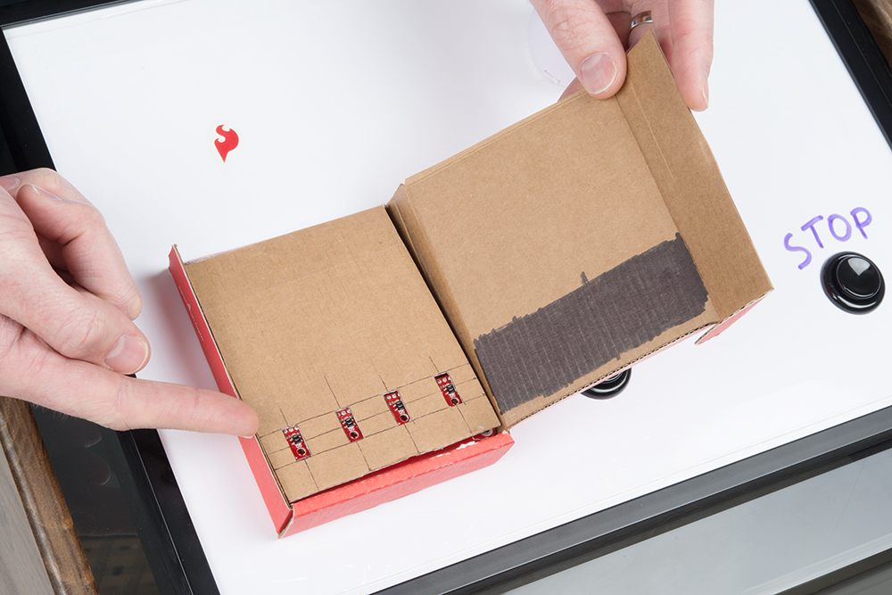
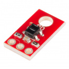
The crafty card reader uses four IR readers facing upwards to look at the cards pattern of black and white squares.
Exposed sensors. (Click to enlarge.)
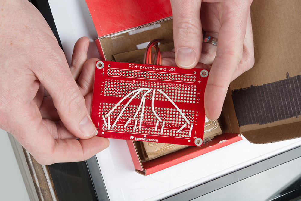
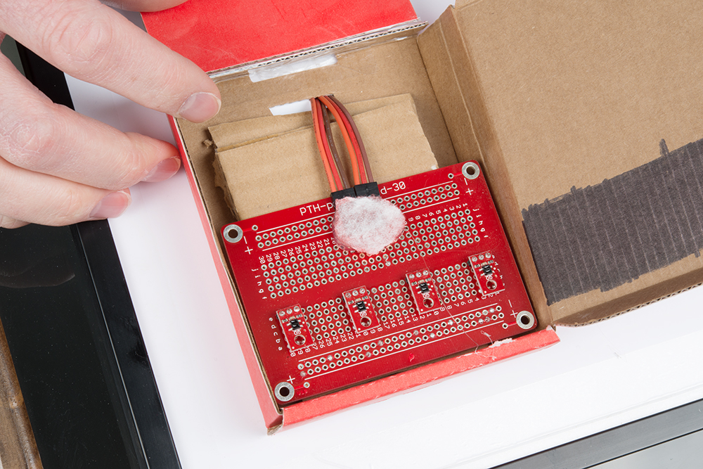
Backside with exposed soldering. (Click to enlarge.)
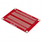
As shown above, it does require a fair amount of soldering. I opted to wire it up on one of our solderable bread board prototyping PCBs. These sensors do a good job at sensing black or white surfaces. They are often used in "line following" applications (like in some of our redbot tutorials).
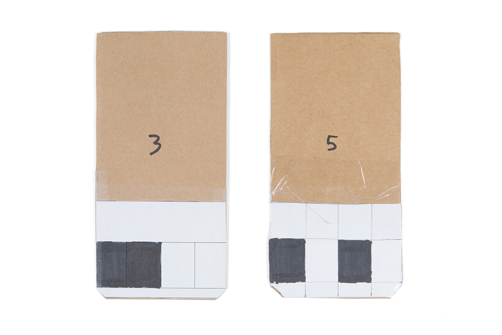
Bottom side of crafty cards. (Click to enlarge.)

Six card "stickers". (Click to enlarge.)
On the left are a couple finished crafty cards. On the right are some more example "stickers" that could be used to make more cards. A black box will be read as a "cleared" or "zero" bit, and a white box will be read as a "set" or "one" bit.
Turns out these readers change dramatically with distance. They work great as line followers on a robot because they are usually at a very consistent distance from the floor surface. Well, with my card reader idea, my cards were not holding position so perfectly inside the reader box. Luckily, I was able to add a little more cardboard and make sort of a "wedge" inside the reader. This held the input cards at a more consistent distance from the IR readers. They were basically touching the readers, but that turned out okay!
Additional Tools and Materials:

Additional Reading:
You will also want to review the following tutorials as well.How to Solder: Through-Hole Soldering
Binary
Wiring
In order to wire up your crafty IR card reader, you will need to review the circuit for the IR sensor. The product page and bildr tutorial are both good resources.
The four IR sensors in this project are wired up so that each output is connected to Arduino pins: 4,5,6,7. You also need to power each IR sensor with 5V and GND. For my hookup, I chose to use Arduino pins D2 and D3 for power. Set D2 to an OUTPUT HIGH (5V power) and D3 to an OUTPUT LOW (GND). You could choose to use the 5V pin and GND pin on the Redboard Qwiic, but I chose to use D2/D3 for power so that I could plug all of my lines from the IR sensors into a single row of six pins.
Resources and Going Further
If you've made it this far into the tutorial, we hope you are happy with a completed jukebox of your own! If you are having any trouble, or have some more questions, please feel free to reach out in the comments below or on our forum.
For more information, check out the resources below:
- GitHub Project Repository
- SparkFun MP3 Arduino Library (ZIP)
- SparkFun MP3 Arduino Library GitHub Repository
- SFE Product Showcase
If you'd like to share your project with the SparkFun community or browse to see others, here are some related forum pages:
- SparkFun Forum Discussion: Projects (A great place to share your project and/or ask questions)
- SparkFun Forum Discussion: QWIIC System (Anything with a QWIIC system, post here)
Need some inspiration for your next project? Check out some of these other Qwiic product tutorials: